
Recomendados
Más contenido relacionado
Similar a A Review of the Recent Development in Machining Parameter Optimization
Similar a A Review of the Recent Development in Machining Parameter Optimization (20)
Último
Último (20)
A Review of the Recent Development in Machining Parameter Optimization
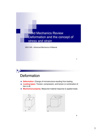
- 1. 1 Solid Mechanics Review Deformation and the concept of stress and strain MCE 508 – Advanced Mechanics of Material 1 Deformation Deformation: Change of microstructure resulting from loading. Loading types: Tension, compression, and torsion or combination of two or all. Mechanical property: Measured material response to applied loads. 2
- 2. 2 Deformation Materials are usually assumed to be Continuous (no cracks or voids). Homogeneous (identical properties at all points). Isotropic (particular property does not vary with direction). Anisotropy in property exists if the property changes with the direction. Most polycrystalline materials especially metals that have equiaxed grains show isotropy in mechanical properties. In deformation, two measured property are very important: stress and strain. 3 Stress A dA A P dA P σ is the average stress and A is the cross-sectional area. Internal resisting force 4
- 3. 3 Stress If the applied load is normal to the acted area then the stress is called normal stress and represented by S or σ (engineering and true stresses). If the load is parallel to the area then the stress is called shear stress and represented by t. For both stresses, normal and shear, the stress is simply found dividing the load by the area. It is assumed that stress is constant, therefore the calculated stress is an average stress, which does not represent stress in micro scale such as stress around voids and etc. 5 Stress Fracture is normally driven by normal stresses and plastic deformation (viscous flow-change in shape) is driven by shear stresses (see Fig. given below, points reorient atoms). 6
- 4. 4 Stress A cos . P A Pz A sin . sin . P A P A cos . sin . P A P A sin . P x zx y zy t t t For a given plane there is only one normal stress and there may be two shear stresses acting on it. 7 Stress-units GPa Pa MPa Pa Pa Pascal m N m kg A P 1 10 , 1 10 ) ( 9 6 2 2 8
- 5. 5 Strain ) ( ) ( strain Normal L L L L length initial elongation strain e o o o 9 Strain ) ( tan strain Shear h a 10
- 6. 6 Tensile test 1. ELASTIC DEFORMATION 2. PLASTIC DEFORMATION 11 Elastic deformation •Stress proportional to strainknown as Hooke’s Law: Material obeying Hooke’s law called linear elastic or Hokean solids. Hooke’s Law is not valid for every material, such as Rubber E is the Elastic Modulus or Young’s Modulus. 12
- 7. 7 Elastic deformation Reversible Process; upon releasing the load strain goes back to zero. Immediate response Linear elastic. time dependent elastic recovery viscoelastic materials. 13 Elastic deformation During elastic deformation volume of the material changes: atomic distance increases/decreases with increasing loading 0 V E is structure insensitive property; metallurgical processes have little effect on it. It is mainly determined by the binding forces between atoms. (E decreases with increasing temperature) For shear stress and strain (t) Hooke’s law still valid but in this case the relation becomes t t G . G E 14
- 8. 8 Onset of plastic deformation Elastic limit: requires precise instruments such as strain gages and strain measuring systems. Proportional limit: stress at which S-e curve deviates from linearity. Yield strength: (offset yield strength or proof strength) stress that produces a small amount of permanent deformation, generally at 0.002 (0.2%) offset strain. 15 Plastic deformation Permanent deformation (irreversible) Density changes little with plastic deformation and therefore it is assumed that volume change is zero (compare with elastic deformation). Plastic deformation changes only the shape of the material. p e t e e e e t p e e e 0 V 16
- 9. 9 Plastic deformation Plastic deformation proceeds by breaking and reestablishing the atomic bonds. In metals, plastic deformation occurs via dislocation motion. 17 Necking Necking starts when the maximum load is reached (Ultimate Tensile Strength (UTS)). Deformation then proceeds in the necked region until the material fails (fracture). 0 dA . d . A dP A P A dA d 18
- 10. 10 True stress-strain L dL d o L o L L L ln L dL (true or logarithmic strain) ) e 1 ln( L ) L ( ln o o L L A A A A L L AL L A 0 V o o o o o o ) 1 ( e S L L Ao P A P o For small strains =S and =e 19 Ductility Percent elongation Percent reduction in area It shows material ability to deform plastically o o f L L L E % o f o A A A A % 20
- 11. 11 Stress at a point 3-Normal stresses: x,y,z 6 shear stresses: txy, txz ,tyx ,tyz ,tzx ,tzy Notation: x: Normal stress acting in x- direction. txy: x is the plane on which the stress acts and y is the direction. Plane Direction Value - - + + - - - + - + + + Value of shear stress 21 Stress at a point Summation of the moments of forces about z axis; y z x yx x z y xy ) ( ) ( t t yx xy t t zy yz zx xz , t t t t State of stress at a point is described completely by six components of stress; 3 normal and 3 shear stresses. 22
- 12. 12 Plane stress plane stress condition: z=0, txz=tyz=0, L and w >>t 0 Fx t sin m , cos l sin . A . cos . A . A S yx x x m . A . l . A . A . S yx x x t l . A . m . A . A . S xy y y t l . m . S xy y y t m . S l . S sin . S cos . S ' y x y x x m . l . S yx x x t (A) 23 t sin . cos . . 2 sin . cos . ) ( ' xy 2 y 2 x x Plane stress m ). m . l . ( l ). l . m . ( m . S l . S yx x xy y x y ' y ' x t t t t t cos . sin ). ( ) sin (cos ) ( x y 2 2 xy ' y ' x ) 2 sin( ). 2 cos( . . 2 ) 2 ( sin . ) 2 ( cos . ) 2 ( ' xy 2 y 2 x x t t sin . cos . . 2 cos . sin . ) ( ' xy 2 y 2 x y 2 2 cos 1 sin 2 1 2 cos cos 2 2 2 cos sin cos 2 sin cos . sin . 2 2 2 t 2 sin . 2 cos . 2 2 ) ( ' xy y x y x x t 2 sin . 2 cos . 2 2 ) ( ' xy y x y x y t t 2 cos . 2 sin . 2 ) ( xy x y ' y ' x 24
- 13. 13 -40 -20 0 20 40 60 80 100 0 40 80 120 160 stress(MPa) Teta max min max min t t 45 o 45 o Max. and min normal stresses occur when t=0 Max. and min. values and t occur 90o apart tmax at an angle halfway between max and min and t change in the form of sine wave, with a period of 180o 25 Example -15 -10 -5 0 5 10 15 0 40 80 120 160 stress(MPa) Teta max min max min t t 45 o 26
- 14. 14 Example -40 -20 0 20 40 60 0 60 120 180 stress(MPa) Teta max min max min t t 45 o 25 MPa x=50 MPa 27 Principal planes and stresses Principle Plane: plane on which no shear stress acts (shear stress=0), plane of maximum and minimum normal stresses. Normal stresses acting on principle planes are called principle stresses. For 2D case: max=1 and min=2 For 3D case: max=1 and min=3 The direction of principal stresses are the principal directions and shown as 1, 2, and 3. 28
- 15. 15 Principal planes and stresses Since there is no shear stresses on the principal plane; 2 2 2 tan 0 2 cos . 2 sin 2 ) ( 1 2 1 ' ' t t t n and root two with y x xy xy x y y x 29 Principal planes and stresses o o o o y x xy and 05 . 172 90 5 . 82 5 . 82 90 95 . 7 95 . 7 15 2 70 20 10 80 ) 10 . 2 ( 2 2 tan 2 , 1 2 , 1 t x=80 MPa y=10 MPa txy=-10 MPa o o max 180 135 between o 2 o 1 5 . 82 and 05 . 172 30
- 16. 16 Principal planes and stresses y x xy t 2 2 tan 2 y x 2 xy xy ) 2 ( 2 sin t t 2 y x 2 xy y x ) 2 ( 2 ) ( 2 cos t 2 y x 2 xy xy xy 2 y x 2 xy y x y x y x x ) 2 ( . ) 2 ( 2 ) ( . 2 2 ) ( ' t t t t 2 y x 2 xy y x 2 , 1 min max, ) 2 ( 2 t 2 31 Maximum and minimum shear stresses To find tmax,min 0 2 sin . . 2 ) ( 0 d d xy y x ' y ' x t t xy y x s t 2 2 tan 2 y x 2 xy min max, s ' y ' x ) 2 ( ) ( t t t max min max 2 t 32
- 17. 17 Example x=80 MPa y=10 MPa txy=-10 MPa 2 y x 2 xy y x 2 , 1 min max, ) 2 ( 2 t 2 ) 2 10 80 ( ) 10 ( 2 10 80 2 2 , 1 4 . 36 45 2 , 1 MPa 4 . 81 4 . 36 45 1 MPa 6 . 8 4 . 36 45 2 MPa 4 . 36 min max, t 33 Strain at a point x u dx dx dx x u dx exx y v eyy z w ezz z e y e x e w z e y e x e v z e y e x e u zz zy zx yz yy yx xz xy xx j ij i x e u where i free suffix and jdummy suffix (x,y,z) 34
- 18. 18 Strain at a point z w y w x w z v y v x v z u y u x u e e e e e e e e e e zz zy zx yz yy yx xz xy xx ij exy=eyxPure shear exy=-eyxpure rotation ij ij ji ij ji ij ij ) e e ( 2 1 ) e e ( 2 1 e xy i j j i ij ) x v y u ( 2 1 ) x u x u ( 2 1 xy i j j i ij ) x v y u ( 2 1 ) x u x u ( 2 1 Displacement tensor 35 Strain at a point x v y u xy x w z u xz z v y w yz ij ij 2 z w ) y w z v ( 2 1 ) x w z u ( 2 1 ) y w z v ( 2 1 y v ) x v y u ( 2 1 ) x w z u ( 2 1 ) x v y u ( 2 1 x u zz zy zx yz yy yx xz xy xx ij 0 ) y w z v ( 2 1 ) x w z u ( 2 1 ) y w z v ( 2 1 0 ) x v y u ( 2 1 ) x w z u ( 2 1 ) x v y u ( 2 1 0 zz zy zx yz yy yx xz xy xx ij 36
- 19. 19 Poissons’ ratio x x E E v v E x x z y x x Where v Poisson’s Ratio Perfectly isotropic material v=0.25 For most metals v~0.33 x y v 37 Uniaxial tension or compression. Constitutive Equations ) ( v E 1 z y x x ) ( v E 1 x z y y ) ( v E 1 y x z z xy xy G t yz yz G t xz xz G t ) m z y x z y x E v E v 3 2 1 2 1 38
- 20. 20 Bulk and Shear Modulus Stress-strain relation for isotropic material involves three constants, E, G, and v. Bulk Modulus (K) 1 P strain volume pressure c hydrostati K m ) v 2 1 ( 3 E K Shear Modulus (G): ) v 1 ( 2 E G 39 Constitutive Equations ) ( E v E ) v 1 ( E v E v E v E v E z y x x x x z y x x ij kk ij ij E v ) E v 1 ( ) 1 )( ( E v E ) v 1 ( zz yy xx xx xx i=j=x ) ( v E 1 zz yy xx xx ) 0 )( ( E v E ) v 1 ( 2 kk xy xy xy t i=x and j=y ) v 1 ( 2 E G ) v 1 ( 2 E E ) v 1 ( 2 xx xy xy xy t t 40
- 21. 21 Constitutive Equations ) ( ) v 2 1 ( E ) ( z y x z y x ) ( E v E ) v 1 ( z y x x x ) ( ) v 2 1 )( v 1 ( vE ) v 1 ( E z y x x x ij kk ij ij ) v 2 1 )( v 1 ( vE ) v 1 ( E t tan cons s ' Lame ) v 2 1 )( v 1 ( vE ij kk ij ij ) v 1 ( E x z y x x x G 2 ) 1 )( ( ) v 1 ( E ' G 2 ' v 1 E ' ij ij ij kk kk ii K 3 v 2 1 E 41 Constitutive Equations kl ijkl ij S kl ijkl ij C where Sijkl is the compliance and Cijkl stiffness tensors. S and C are fourth rank tensors with 81 (34) constants. 12 31 23 33 22 11 12 13 23 33 22 11 G 0 0 0 0 0 0 G 0 0 0 0 0 0 G 0 0 0 0 0 0 ) v 1 )( v 2 1 ( ) v 1 ( E ) v 1 )( v 2 1 ( ) v 1 ( E ) v 1 )( v 2 1 ( ) v 1 ( E 0 0 0 ) v 1 )( v 2 1 ( ) v 1 ( E ) v 1 )( v 2 1 ( ) v 1 ( E ) v 1 )( v 2 1 ( ) v 1 ( E 0 0 0 ) v 1 )( v 2 1 ( Ev ) v 1 )( v 2 1 ( Ev ) v 1 )( v 2 1 ( ) v 1 ( E t t t 42