SlideShare una empresa de Scribd logo
1 de 4
DESIGN ANALYSIS OF UAV (UNMANNED AIR VEHICLE) USING NACA 0012 AEROFOIL PROFILE

                     Alimul Rajib1, Bhuiyan Shameem Mahmud Ebna Hai1 and Md Abdus Salam2
 1
    Department of Mechanical Engineering, Military Institute of Science and Technology, Dhaka-1216, Bangladesh.
2
    Department of Aeronautical Engineering, Military Institute of Science and Technology, Dhaka-1216, Bangladesh.


      ABSTRACT
      This research work is concerned with the application of conceptual design of Unmanned Air Vehicle (UAV).
      UAV is used for surveillance and reconnaissance to serve for the defense as well as national security and
      intelligence purpose. Here NACA 0012 aerofoil profile is used to design UAV by using CFD (Computational
      Fluid Dynamics) software. The aim of this research is to investigate the flow patterns and determine the
      aerodynamic characteristics of NACA 0012 profile by varying the angle of attack and Reynolds Number
      numerically. The research is carried out with symmetric aerofoil with the chord length of 0.1m. The research
      work explained different aerodynamic characteristics like lift force and drag force, lift and drag coefficient,
      pressure distribution over aerofoil etc

      Keywords: UAV, CFD, NACA 0012.


                                                                    The lift force increases almost linearly with the angle of
1. INTRODUCTION
An Unmanned Air Vehicle (UAV) is an unpiloted                       attack until a maximum value is reached where upon
aircraft. Its aerodynamic characteristics vary with                 the wing is said to stall. The shape of the drag force vs.
certain parameters like the angle of attack and others.             angle of attack is approximately parabolic. It is
Experimental works on UAVs have been conducted in                   desirable for the wing to have the maximum lift and
many places with various aerofoil profiles but not                  smallest possible drag.
enough work with the Computational Fluid Dynamics
(CFD) analysis is not available that much till now. The             1.1 BACKGROUND OF THE RESEARCH WORK
present work contains mainly CFD analysis to                        Designing of UAVs requires designing of aerofoil
determine the flow pattern and the aerodynamic                      section. Various aerofoil configurations have been
characteristics of an UAV.                                          employed so far and more will be coming. The present
The shape of an aircraft is designed to make the airflow            work is carried out numerically with CFD analysis for
through the surface to produce a lifting force in the               NACA 0012 symmetric aerofoil profile. Some of the
most efficient manner. In addition to the lift, a force             parameters of aerofoil and properties of air have been
directly opposing the motion of the wing through the                kept constant and some have been varied.
air is always present, which is called a drag force. The            The flow of air over the aerofoil is varied as per
angle between the relative wind and the chord line is               requirement. The chord length of the aerofoil is
the angle of attack of the aerofoil. The lift and drag              100mm. The free stream airflow has been kept 12.5 m/s
forces developed by an aircraft will vary with the                  and the effect of the temperature in the study has been
                                                                    neglected. The density of air (ρo)= 1.22 kg/m3,
change of angle of attack. The cross sectional shape
obtained by the intersection of the wing with the                   operating pressure (Po) = 0.101 MPa (1.01 bar) and
                                                                    absolute viscosity (μ) = 1.789 x 10⁻⁵ kg/m-s. The
perpendicular plane is called an aerofoil. Here NACA
0012 symmetric aerofoil profiles have been used for the             Reynolds Number has been considered as variable. The
present research work.                                              data have been obtained at different angles of attack
                                                                    starting from 0o with 1o incremental step.
                                                                    The various measurement characteristics such as
                                                                    pressure distribution, pressure contours, Mach number,
                                                                    etc. around a two dimensional aerofoils of UAV varies
                                                                    with the angle of attack.
                                                                    The aerodynamic characteristics of a typical aircraft can
                                                                    also be experimentally investigated in the wind tunnels.
                                                                    The surface static pressure is measured from the suction
                                                                    and the pressure side of the aerofoil through different
                                                                    pressure     tapping      points.    The      aerodynamic
                                                                    characteristics for different configurations are
                                                                    determined from the static pressure distribution over
                                                                    the surfaces of aerofoils at different angles of attack.

Fig 1: Aerodynamic forces on a typical aerofoil
1.2 OBJECTIVES                                                                             2.2 AEROFOIL DESIGN
  a. Designing of NACA 0012 aerofoil section and                                           The vertices obtained from the C program were used to
     investigation of the flow pattern with the help of                                    draw the profile line which was as follows:
     CFD software.
  b. Determination of the surface static pressure
     distribution, pressure contours, Mach number on
     the aerofoils in the biplane configuration.
  c. Determination of the aerodynamic characteristics
     from the static pressure distributions.
  d. Discussion on the computational results of the
                                                                                           Fig 3: NACA 0012 aerofoil section.
     CFD analysis.
                                                                                           The boundary was then given.
2. WORKING PRINCIPAL
The computation and graphical plotting involves the
                                                                                           Table 1: Values of boundary vertices for NACA 0012
following sequence:
                                                                                           aerofoil profile.
   a. Programming to get vertices for aerofoil section
      using governing equation.
                                                                                            Label        X              Y             Z
   b. Working with vertices using GAMBIT software.
                                                                                            A            0.1            1.25          0
   c. Working with FLUENT software.
                                                                                            B            2.1            1.25          0
                                                                                            C            2.1            0             0
2.1 DESIGN METHOD
                                                                                            D            2.1            -0.25         0
The early NACA aerofoil series, the 4-digit was
                                                                                            E            0.1            -0.25         0
generated using analytical equations that describe its
                                                                                            F            -1.15          0             0
geometrical feature.
                                                                                            G            0.1            0             0

                                                                                           The boundaries were chosen such to get uniform
                                                                                           meshing. Line and face both the meshing were
                                                                                           employed here. To mesh, interval counts and successive
                                                                                           ratios were used here.
                                                                                           After employing boundary and meshing the following
                                                                                           meshed geometry was found.

Fig 2: NACA aerofoil geometrical construction.

The first digit specifies the maximum camber (m) in
percentage of the chord, the second indicates the
position of the maximum camber (p) in tenths of chord,
and the last two numbers provide the maximum
thickness (t) of the aerofoil in percentage of chord. So,
our concerned NACA 0012 aerofoil means 0% camber
at 0 (zero) position (as there is no camber) and
thickness of .012m. The thickness distribution above
(+) and below (-) the mean line was calculated by
plugging the value of t into the following equation for
each of the x coordinates.


                                                                                      
          t
                                                                                           Fig 4: Meshing of aerofoil section (2D).
 yt                    x  0 . 1260 x  0 . 3516 x 2  0 . 2843 x 3  0 . 1015 x 4
              0 . 2969
         0 .2

                                                                                           It was recommended that the boundaries around the
The equation was solved here by a C program to find
                                                                                           aerofoil were far enough.
vertices for the aerofoil line. Approximately, 10,000
vertices were used.
                                                                                           2.3 Analysis of Data in Fluent
                                                                                           The mesh file was imported to the Fluent and it
                                                                                           required certain features. First of all, 2-D mode was
                                                                                           selected. The parameters which needed to be constant
                                                                                           were: pressure (atmospheric pressure = 101325 Pa), air
                                                                                           velocity (v = 12.5 m/s), density of air (ρ = 1.225
                                                                                           kg/m3), absolute viscosity (μ = 1.789 x 10⁻⁵ kg/m-s).
                                                                                           The Reynolds number and Mach number were kept
                                                                                           constant and sometimes varied as per requirement.
3. RESULTS AND GRAPHS                                                               3.4 Angle of attack Vs Drag coefficient:
3.1 Lift coefficient (CL)
Sample results of lift coefficient CL with variable angle
                                                                                                         0.025
of attack α and Reynolds number Re are as follows:
Table3. Values of CL:                                                                                     0.02


                                                                                      Lift coefficient
 Re                            CL                                                                        0.015

  α 3.6 x 10⁵ 7 x 10⁵ 1 x 10⁶ 2 x 10⁶ 5 x 10⁶                                                             0.01
  0 0.0000         0.0000 0.0000 0.0000 0.0000                                                           0.005
  2 0.2200         0.2200 0.2200 0.2200 0.2200                                                              0
  4 0.4400         0.4400 0.4400 0.4400 0.4400                                                                   0   2       4        6        8      10     12       14
  6 0.6600         0.6600 0.6600 0.6600 0.6600                                                                                      Angle of attack

  8 0.8542         0.8800 0.8800 0.8800 0.8800                                                                       Re = 360000       Re = 700000     Re = 1000000
 10 0.9811         1.0343 1.0512 1.0727 1.1000                                                                       Re = 2000000      Re = 5000000
 12 0.9132         1.0390 1.1212 1.2072 1.2673
 14 -              0.6284 0.8846 1.1614 1.3423                                      Fig 6: Angle of attack Vs Drag coefficient for several
                                                                                    Reynolds number (Re).
3.2 Drag coefficient (CD)
Table2. Values of CD.                                                               3.5 Pressure Distribution over NACA 0012 Aerofoil
  Re                       CD
  α 3.6 x 10⁵ 7 x 10⁵ 1 x 10⁶                                  2 x 10⁶    5 x 10⁶
  0     0.0079     0.0067 0.0065                               0.0064     0.0064
  2     0.0084     0.0070 0.0068                               0.0066     0.0066
  4     0.0098     0.0083 0.0078                               0.0073     0.0072
  6     0.0125     0.0108 0.0101                               0.0090     0.0081
  8     0.0153     0.0128 0.0119                               0.0105     0.0092
  10    0.0184     0.0159 0.0147                               0.0128     0.0106
  12    0.0217     0.0195 0.0180                               0.0155     0.0130
  14       -       0.0236 0.0222                               0.0191     0.0159

These values are used to find the graphs: (a) lift
coefficient vs. angle of attack and (b) drag coefficient
vs. angle of attack graphs for various Reynolds number.

3.3 Lift coefficient Vs Angle of attack:
                                                                                    Fig 7: The pressure distribution for the NACA 0012
                                                                                    aerofoil under free stream condition for Mach number
                    1.6
                                                                                    0.7 and angle of attack 4o.
                    1.4
                    1.2
 Lift coefficient


                      1
                    0.8
                    0.6
                    0.4
                    0.2
                      0
                          0        5               10           15            20
                                             Angle of attack

                              Re = 360000       Re = 700000    Re = 1000000
                              Re = 2000000      Re = 5000000


Fig 5: Lift coefficient Vs Angle of attack for several
Reynolds number (Re).

This graph shows that maximum lift coefficient is not
constant for NACA 0012 aerofoil, it increases with the
increasing Reynolds number with angle of attack.
                                                                                    Fig 8: The pressure distribution for the NACA 0012
                                                                                    aerofoil for inviscid flow for Mach number 0.8 and
                                                                                    angle of attack 2o.
7. NOMENCLATURE

                                                                Symbol   Meaning              Unit
                                                                  α      Angle of attack      Degree
                                                                  Re     Reynolds number      None
                                                                  CL     Lift coefficient     None
                                                                  CD     Drag coefficient     None
                                                                                              kg/m3
                                                                  ρo     Density of air
                                                                  Po     Operating pressure   MPa
                                                                  μ      Absolute viscosity   kg/m-s
                                                                  v      air velocity         m/s


Fig 9: The pressure distribution for the NACA 0012
aerofoil for viscid flow for Mach number 0.7 and angle
of attack 4o.

4. DISCUSSION
From Fig 5 it is seen that at zero degree angle of attack
the lift coefficient is zero and it increases linearly with
the increase of angle of attack. After reaching at a peak
point, the lift coefficient decreases sharply with the
increase of angle of attack and the values also vary with
different Reynolds number.
One major feature of drag coefficient is that for zero
degree angle of attack it is not zero and so thus the drag
force. From Fig 6, parabolic curves are found as were
expected.

5. CONCLUSION
This research work has been carried out to observe the
characteristics of UAV NACA 0012. This mainly
involved the conceptual design for better design and
economical construction. The design concept is a better
approach to choose among various types of UAV
(Unmanned Air Vehicle). Mainly, this work has brought
some important aerodynamic characteristics of
aerofoils. These results found in two dimensional
designs may vary with the three dimensional.

6. REFERENCES
1. Sq Ldr GM Jahangir Alam, 2007, “Investigation Of
    The Aerodynamic Characteristics Of The Biplane
    Configurations Using NACA 0024 Profile”, M. Sc.
    Thesis, BUET, Dhaka, Bangladesh.
2. J. N. Reddy, 2005, Finite Element Method, Texas A
    & M University, Texas.
3. Byron S. Gottfried, 1996, Schaum’s Outline Of
    Theory And Problems Of Programming With C
4. Rajesh Bhaskaran, Fluent Tutorials.
5. James C. Date and Stephen R. Turnock, 2002,
    “Computational Evaluation Of The Periodic
    Performance Of A NACA 0012 Fitted With A
    Gurney Flap”.
6. Bertin J.J, Smith M.L., “Aerodynamics for
    Engineers”, 3rd – Ed, Prentice Hall.
7. Clancy, L. J., “Aerodynamics”.

Más contenido relacionado

La actualidad más candente

ME6603 - FINITE ELEMENT ANALYSIS UNIT - II NOTES AND QUESTION BANK
ME6603 - FINITE ELEMENT ANALYSIS UNIT - II NOTES AND QUESTION BANKME6603 - FINITE ELEMENT ANALYSIS UNIT - II NOTES AND QUESTION BANK
ME6603 - FINITE ELEMENT ANALYSIS UNIT - II NOTES AND QUESTION BANKASHOK KUMAR RAJENDRAN
 
CFD analysis of aerofoil
CFD analysis of aerofoilCFD analysis of aerofoil
CFD analysis of aerofoilNeel Thakkar
 
Propeller & Fan Design Optimization
Propeller & Fan Design Optimization Propeller & Fan Design Optimization
Propeller & Fan Design Optimization SimScale
 
ME6603 - FINITE ELEMENT ANALYSIS UNIT - III NOTES AND QUESTION BANK
ME6603 - FINITE ELEMENT ANALYSIS UNIT - III NOTES AND QUESTION BANKME6603 - FINITE ELEMENT ANALYSIS UNIT - III NOTES AND QUESTION BANK
ME6603 - FINITE ELEMENT ANALYSIS UNIT - III NOTES AND QUESTION BANKASHOK KUMAR RAJENDRAN
 
Basic Aerodynamics.Ppt
Basic Aerodynamics.PptBasic Aerodynamics.Ppt
Basic Aerodynamics.Pptazfa
 
Meshing in FEA - Why Do We Carry Out Meshing?
Meshing in FEA - Why Do We Carry Out Meshing?Meshing in FEA - Why Do We Carry Out Meshing?
Meshing in FEA - Why Do We Carry Out Meshing?Engineering Technique
 
Buckling and tension field beam for aerospace structures
Buckling and tension field beam for aerospace structuresBuckling and tension field beam for aerospace structures
Buckling and tension field beam for aerospace structuresMahdi Damghani
 
ME6603 - FINITE ELEMENT ANALYSIS UNIT - V NOTES AND QUESTION BANK
ME6603 - FINITE ELEMENT ANALYSIS UNIT - V NOTES AND QUESTION BANKME6603 - FINITE ELEMENT ANALYSIS UNIT - V NOTES AND QUESTION BANK
ME6603 - FINITE ELEMENT ANALYSIS UNIT - V NOTES AND QUESTION BANKASHOK KUMAR RAJENDRAN
 
Properties of surfaces-Centre of gravity and Moment of Inertia
Properties of surfaces-Centre of gravity and Moment of InertiaProperties of surfaces-Centre of gravity and Moment of Inertia
Properties of surfaces-Centre of gravity and Moment of InertiaJISHNU V
 
Concentric springs, surge phenomenon in spring, helical torsion, spiral spring
Concentric springs, surge phenomenon in spring, helical torsion, spiral springConcentric springs, surge phenomenon in spring, helical torsion, spiral spring
Concentric springs, surge phenomenon in spring, helical torsion, spiral springvaibhav tailor
 

La actualidad más candente (20)

ME6603 - FINITE ELEMENT ANALYSIS UNIT - II NOTES AND QUESTION BANK
ME6603 - FINITE ELEMENT ANALYSIS UNIT - II NOTES AND QUESTION BANKME6603 - FINITE ELEMENT ANALYSIS UNIT - II NOTES AND QUESTION BANK
ME6603 - FINITE ELEMENT ANALYSIS UNIT - II NOTES AND QUESTION BANK
 
CFD analysis of aerofoil
CFD analysis of aerofoilCFD analysis of aerofoil
CFD analysis of aerofoil
 
Plate with a hole
Plate with a holePlate with a hole
Plate with a hole
 
Propeller & Fan Design Optimization
Propeller & Fan Design Optimization Propeller & Fan Design Optimization
Propeller & Fan Design Optimization
 
Engineering manuval.pdf
Engineering manuval.pdfEngineering manuval.pdf
Engineering manuval.pdf
 
ME6603 - FINITE ELEMENT ANALYSIS UNIT - III NOTES AND QUESTION BANK
ME6603 - FINITE ELEMENT ANALYSIS UNIT - III NOTES AND QUESTION BANKME6603 - FINITE ELEMENT ANALYSIS UNIT - III NOTES AND QUESTION BANK
ME6603 - FINITE ELEMENT ANALYSIS UNIT - III NOTES AND QUESTION BANK
 
Shear Stress; Id no.: 10.01.03.033
Shear Stress; Id no.: 10.01.03.033Shear Stress; Id no.: 10.01.03.033
Shear Stress; Id no.: 10.01.03.033
 
Basic Aerodynamics.Ppt
Basic Aerodynamics.PptBasic Aerodynamics.Ppt
Basic Aerodynamics.Ppt
 
Wind tunnel design
Wind tunnel designWind tunnel design
Wind tunnel design
 
morphing wings
morphing wingsmorphing wings
morphing wings
 
Meshing in FEA - Why Do We Carry Out Meshing?
Meshing in FEA - Why Do We Carry Out Meshing?Meshing in FEA - Why Do We Carry Out Meshing?
Meshing in FEA - Why Do We Carry Out Meshing?
 
Buckling and tension field beam for aerospace structures
Buckling and tension field beam for aerospace structuresBuckling and tension field beam for aerospace structures
Buckling and tension field beam for aerospace structures
 
ME6603 - FINITE ELEMENT ANALYSIS UNIT - V NOTES AND QUESTION BANK
ME6603 - FINITE ELEMENT ANALYSIS UNIT - V NOTES AND QUESTION BANKME6603 - FINITE ELEMENT ANALYSIS UNIT - V NOTES AND QUESTION BANK
ME6603 - FINITE ELEMENT ANALYSIS UNIT - V NOTES AND QUESTION BANK
 
Properties of surfaces-Centre of gravity and Moment of Inertia
Properties of surfaces-Centre of gravity and Moment of InertiaProperties of surfaces-Centre of gravity and Moment of Inertia
Properties of surfaces-Centre of gravity and Moment of Inertia
 
Wind Tunnel Ex
Wind Tunnel ExWind Tunnel Ex
Wind Tunnel Ex
 
CFD analysis of an Airfoil
CFD analysis of an AirfoilCFD analysis of an Airfoil
CFD analysis of an Airfoil
 
Concentric springs, surge phenomenon in spring, helical torsion, spiral spring
Concentric springs, surge phenomenon in spring, helical torsion, spiral springConcentric springs, surge phenomenon in spring, helical torsion, spiral spring
Concentric springs, surge phenomenon in spring, helical torsion, spiral spring
 
CENTROID
CENTROIDCENTROID
CENTROID
 
HYPERSONIC VEHICLES
HYPERSONIC VEHICLESHYPERSONIC VEHICLES
HYPERSONIC VEHICLES
 
Lecture 11 & 12
Lecture 11 & 12Lecture 11 & 12
Lecture 11 & 12
 

Destacado

NACA 8414 PROFİLİNE SAHİP UÇAK KANADININ CFD İLE AERODİNAMİK ANALİZİ
NACA 8414 PROFİLİNE SAHİP UÇAK KANADININ CFD İLE AERODİNAMİK ANALİZİNACA 8414 PROFİLİNE SAHİP UÇAK KANADININ CFD İLE AERODİNAMİK ANALİZİ
NACA 8414 PROFİLİNE SAHİP UÇAK KANADININ CFD İLE AERODİNAMİK ANALİZİKenan Çal
 
Uçak Kanadında Titreşim Analizi-Modal Analysis of Wing Structure
Uçak Kanadında Titreşim Analizi-Modal Analysis of Wing StructureUçak Kanadında Titreşim Analizi-Modal Analysis of Wing Structure
Uçak Kanadında Titreşim Analizi-Modal Analysis of Wing Structuretst34
 
Aer 101 chapter 5
Aer 101 chapter 5Aer 101 chapter 5
Aer 101 chapter 5anashalim
 
Fluid motion in the posterior chamber of the eye
Fluid motion in the posterior chamber of the eyeFluid motion in the posterior chamber of the eye
Fluid motion in the posterior chamber of the eyeDr. Bhuiyan S. M. Ebna Hai
 
Study of wind effect on building with hexagonal cross section
Study of wind effect on building with hexagonal cross sectionStudy of wind effect on building with hexagonal cross section
Study of wind effect on building with hexagonal cross sectionDr. Bhuiyan S. M. Ebna Hai
 
2412 ICC Company Presentation
2412 ICC Company Presentation2412 ICC Company Presentation
2412 ICC Company Presentationmhimcc
 
Flowdirection
FlowdirectionFlowdirection
FlowdirectionApoorv00
 
Naca 2415 finding lift coefficient using cfd, theoretical and javafoil
Naca 2415  finding lift coefficient using cfd, theoretical and javafoilNaca 2415  finding lift coefficient using cfd, theoretical and javafoil
Naca 2415 finding lift coefficient using cfd, theoretical and javafoileSAT Journals
 
JacobSiegler_Research_2015
JacobSiegler_Research_2015JacobSiegler_Research_2015
JacobSiegler_Research_2015Jacob Siegler
 
A comparative flow analysis of naca 6409 and naca 4412 aerofoil
A comparative flow analysis of naca 6409 and naca 4412 aerofoilA comparative flow analysis of naca 6409 and naca 4412 aerofoil
A comparative flow analysis of naca 6409 and naca 4412 aerofoileSAT Journals
 
Effect of spikes integrated to airfoil at supersonic speed
Effect of spikes integrated to airfoil at supersonic speedEffect of spikes integrated to airfoil at supersonic speed
Effect of spikes integrated to airfoil at supersonic speedeSAT Journals
 
Numerical simulation and optimization of high performance supersonic nozzle a...
Numerical simulation and optimization of high performance supersonic nozzle a...Numerical simulation and optimization of high performance supersonic nozzle a...
Numerical simulation and optimization of high performance supersonic nozzle a...eSAT Journals
 
Final Design Report
Final Design ReportFinal Design Report
Final Design ReportJason Ro
 
Hidrolik Yük Asansörü Tasarımı ve Maliyet Analizi
Hidrolik Yük Asansörü Tasarımı ve Maliyet AnaliziHidrolik Yük Asansörü Tasarımı ve Maliyet Analizi
Hidrolik Yük Asansörü Tasarımı ve Maliyet Analizitst34
 

Destacado (20)

NACA 8414 PROFİLİNE SAHİP UÇAK KANADININ CFD İLE AERODİNAMİK ANALİZİ
NACA 8414 PROFİLİNE SAHİP UÇAK KANADININ CFD İLE AERODİNAMİK ANALİZİNACA 8414 PROFİLİNE SAHİP UÇAK KANADININ CFD İLE AERODİNAMİK ANALİZİ
NACA 8414 PROFİLİNE SAHİP UÇAK KANADININ CFD İLE AERODİNAMİK ANALİZİ
 
Uçak Kanadında Titreşim Analizi-Modal Analysis of Wing Structure
Uçak Kanadında Titreşim Analizi-Modal Analysis of Wing StructureUçak Kanadında Titreşim Analizi-Modal Analysis of Wing Structure
Uçak Kanadında Titreşim Analizi-Modal Analysis of Wing Structure
 
Aer 101 chapter 5
Aer 101 chapter 5Aer 101 chapter 5
Aer 101 chapter 5
 
Fluid motion in the posterior chamber of the eye
Fluid motion in the posterior chamber of the eyeFluid motion in the posterior chamber of the eye
Fluid motion in the posterior chamber of the eye
 
Study of Aerodynamics of a Cricket Ball
Study of Aerodynamics of a Cricket BallStudy of Aerodynamics of a Cricket Ball
Study of Aerodynamics of a Cricket Ball
 
A simple model of the liver microcirculation
A simple model of the liver microcirculationA simple model of the liver microcirculation
A simple model of the liver microcirculation
 
Study of wind effect on building with hexagonal cross section
Study of wind effect on building with hexagonal cross sectionStudy of wind effect on building with hexagonal cross section
Study of wind effect on building with hexagonal cross section
 
2412 ICC Company Presentation
2412 ICC Company Presentation2412 ICC Company Presentation
2412 ICC Company Presentation
 
F012413942
F012413942F012413942
F012413942
 
Flowdirection
FlowdirectionFlowdirection
Flowdirection
 
Naca 2415 finding lift coefficient using cfd, theoretical and javafoil
Naca 2415  finding lift coefficient using cfd, theoretical and javafoilNaca 2415  finding lift coefficient using cfd, theoretical and javafoil
Naca 2415 finding lift coefficient using cfd, theoretical and javafoil
 
JacobSiegler_Research_2015
JacobSiegler_Research_2015JacobSiegler_Research_2015
JacobSiegler_Research_2015
 
A comparative flow analysis of naca 6409 and naca 4412 aerofoil
A comparative flow analysis of naca 6409 and naca 4412 aerofoilA comparative flow analysis of naca 6409 and naca 4412 aerofoil
A comparative flow analysis of naca 6409 and naca 4412 aerofoil
 
Effect of spikes integrated to airfoil at supersonic speed
Effect of spikes integrated to airfoil at supersonic speedEffect of spikes integrated to airfoil at supersonic speed
Effect of spikes integrated to airfoil at supersonic speed
 
Numerical simulation and optimization of high performance supersonic nozzle a...
Numerical simulation and optimization of high performance supersonic nozzle a...Numerical simulation and optimization of high performance supersonic nozzle a...
Numerical simulation and optimization of high performance supersonic nozzle a...
 
Cfd notes 1
Cfd notes 1Cfd notes 1
Cfd notes 1
 
Project Full
Project FullProject Full
Project Full
 
Final Design Report
Final Design ReportFinal Design Report
Final Design Report
 
FYP Presentation
FYP PresentationFYP Presentation
FYP Presentation
 
Hidrolik Yük Asansörü Tasarımı ve Maliyet Analizi
Hidrolik Yük Asansörü Tasarımı ve Maliyet AnaliziHidrolik Yük Asansörü Tasarımı ve Maliyet Analizi
Hidrolik Yük Asansörü Tasarımı ve Maliyet Analizi
 

Similar a Design Analysis Of Uav (Unmanned Air Vehicle) Using NACA 0012 Aerofoil Profile

Numerical Analysis of Lift & Drag Performance of NACA0012 Wind Turbine Aerofoil
Numerical Analysis of Lift & Drag Performance of NACA0012 Wind Turbine AerofoilNumerical Analysis of Lift & Drag Performance of NACA0012 Wind Turbine Aerofoil
Numerical Analysis of Lift & Drag Performance of NACA0012 Wind Turbine AerofoilIRJET Journal
 
Optimisation of the design of uav wing j.alexander
Optimisation of the design of uav wing   j.alexanderOptimisation of the design of uav wing   j.alexander
Optimisation of the design of uav wing j.alexandersathyabama
 
Optimisation of the design of uav wing j.alexander, Prakash, BSM Augustine
Optimisation of the design of uav wing   j.alexander, Prakash, BSM AugustineOptimisation of the design of uav wing   j.alexander, Prakash, BSM Augustine
Optimisation of the design of uav wing j.alexander, Prakash, BSM Augustinesathyabama
 
FLOW ANALYSIS OVER NACA AIRFOILS USING FLUENT
FLOW ANALYSIS OVER NACA AIRFOILS USING FLUENTFLOW ANALYSIS OVER NACA AIRFOILS USING FLUENT
FLOW ANALYSIS OVER NACA AIRFOILS USING FLUENTAmiya Kumar Samal
 
Study on Effect of Semi Circular Dimple on Aerodynamic Characteristics of NAC...
Study on Effect of Semi Circular Dimple on Aerodynamic Characteristics of NAC...Study on Effect of Semi Circular Dimple on Aerodynamic Characteristics of NAC...
Study on Effect of Semi Circular Dimple on Aerodynamic Characteristics of NAC...ROSHAN SAH
 
COMPUTATIONAL FLUID DYNAMIC ANALYSIS OF NACA 0006 AEROFOIL AT DIFFERENT PARAM...
COMPUTATIONAL FLUID DYNAMIC ANALYSIS OF NACA 0006 AEROFOIL AT DIFFERENT PARAM...COMPUTATIONAL FLUID DYNAMIC ANALYSIS OF NACA 0006 AEROFOIL AT DIFFERENT PARAM...
COMPUTATIONAL FLUID DYNAMIC ANALYSIS OF NACA 0006 AEROFOIL AT DIFFERENT PARAM...IRJET Journal
 
IRJET- CFD Approach of Joukowski Airfoil (T=12%), Comparison of its Aerodynam...
IRJET- CFD Approach of Joukowski Airfoil (T=12%), Comparison of its Aerodynam...IRJET- CFD Approach of Joukowski Airfoil (T=12%), Comparison of its Aerodynam...
IRJET- CFD Approach of Joukowski Airfoil (T=12%), Comparison of its Aerodynam...IRJET Journal
 
Computational Analysis of the Aerodynamic Performance of NACA 4412 and NACA 2...
Computational Analysis of the Aerodynamic Performance of NACA 4412 and NACA 2...Computational Analysis of the Aerodynamic Performance of NACA 4412 and NACA 2...
Computational Analysis of the Aerodynamic Performance of NACA 4412 and NACA 2...IRJET Journal
 
IRJET- Analysing the Performance of Solar Powered Wing (UAV)
IRJET-  	  Analysing the Performance of Solar Powered Wing (UAV)IRJET-  	  Analysing the Performance of Solar Powered Wing (UAV)
IRJET- Analysing the Performance of Solar Powered Wing (UAV)IRJET Journal
 
IRJET- Particle Swarm Intelligence based Dynamics Economic Dispatch with Dail...
IRJET- Particle Swarm Intelligence based Dynamics Economic Dispatch with Dail...IRJET- Particle Swarm Intelligence based Dynamics Economic Dispatch with Dail...
IRJET- Particle Swarm Intelligence based Dynamics Economic Dispatch with Dail...IRJET Journal
 
Aircraft wing design and strength, stiffness and stability analysis by using...
Aircraft  wing design and strength, stiffness and stability analysis by using...Aircraft  wing design and strength, stiffness and stability analysis by using...
Aircraft wing design and strength, stiffness and stability analysis by using...Mani5436
 
IRJET- Aerodynamic Analysis of Aircraft Wings using CFD
IRJET- Aerodynamic Analysis of Aircraft Wings using CFDIRJET- Aerodynamic Analysis of Aircraft Wings using CFD
IRJET- Aerodynamic Analysis of Aircraft Wings using CFDIRJET Journal
 
reseach journal.pdf
reseach journal.pdfreseach journal.pdf
reseach journal.pdfnareshkotra
 
CFD Analysis of conceptual Aircraft body
CFD Analysis of conceptual Aircraft bodyCFD Analysis of conceptual Aircraft body
CFD Analysis of conceptual Aircraft bodyIRJET Journal
 
IRJET-CFD Analysis of conceptual Aircraft body
IRJET-CFD Analysis of conceptual Aircraft bodyIRJET-CFD Analysis of conceptual Aircraft body
IRJET-CFD Analysis of conceptual Aircraft bodyIRJET Journal
 
ENG687 Aerodynamics.docx
ENG687 Aerodynamics.docxENG687 Aerodynamics.docx
ENG687 Aerodynamics.docx4934bk
 

Similar a Design Analysis Of Uav (Unmanned Air Vehicle) Using NACA 0012 Aerofoil Profile (20)

Numerical Analysis of Lift & Drag Performance of NACA0012 Wind Turbine Aerofoil
Numerical Analysis of Lift & Drag Performance of NACA0012 Wind Turbine AerofoilNumerical Analysis of Lift & Drag Performance of NACA0012 Wind Turbine Aerofoil
Numerical Analysis of Lift & Drag Performance of NACA0012 Wind Turbine Aerofoil
 
Optimisation of the design of uav wing j.alexander
Optimisation of the design of uav wing   j.alexanderOptimisation of the design of uav wing   j.alexander
Optimisation of the design of uav wing j.alexander
 
Optimisation of the design of uav wing j.alexander, Prakash, BSM Augustine
Optimisation of the design of uav wing   j.alexander, Prakash, BSM AugustineOptimisation of the design of uav wing   j.alexander, Prakash, BSM Augustine
Optimisation of the design of uav wing j.alexander, Prakash, BSM Augustine
 
FLOW ANALYSIS OVER NACA AIRFOILS USING FLUENT
FLOW ANALYSIS OVER NACA AIRFOILS USING FLUENTFLOW ANALYSIS OVER NACA AIRFOILS USING FLUENT
FLOW ANALYSIS OVER NACA AIRFOILS USING FLUENT
 
Study on Effect of Semi Circular Dimple on Aerodynamic Characteristics of NAC...
Study on Effect of Semi Circular Dimple on Aerodynamic Characteristics of NAC...Study on Effect of Semi Circular Dimple on Aerodynamic Characteristics of NAC...
Study on Effect of Semi Circular Dimple on Aerodynamic Characteristics of NAC...
 
COMPUTATIONAL FLUID DYNAMIC ANALYSIS OF NACA 0006 AEROFOIL AT DIFFERENT PARAM...
COMPUTATIONAL FLUID DYNAMIC ANALYSIS OF NACA 0006 AEROFOIL AT DIFFERENT PARAM...COMPUTATIONAL FLUID DYNAMIC ANALYSIS OF NACA 0006 AEROFOIL AT DIFFERENT PARAM...
COMPUTATIONAL FLUID DYNAMIC ANALYSIS OF NACA 0006 AEROFOIL AT DIFFERENT PARAM...
 
IRJET- CFD Approach of Joukowski Airfoil (T=12%), Comparison of its Aerodynam...
IRJET- CFD Approach of Joukowski Airfoil (T=12%), Comparison of its Aerodynam...IRJET- CFD Approach of Joukowski Airfoil (T=12%), Comparison of its Aerodynam...
IRJET- CFD Approach of Joukowski Airfoil (T=12%), Comparison of its Aerodynam...
 
CFD analysis of bio-inspired corrugated airfoils
CFD analysis of bio-inspired corrugated airfoilsCFD analysis of bio-inspired corrugated airfoils
CFD analysis of bio-inspired corrugated airfoils
 
C1304021824
C1304021824C1304021824
C1304021824
 
cfd naca0012
cfd naca0012cfd naca0012
cfd naca0012
 
Computational Analysis of the Aerodynamic Performance of NACA 4412 and NACA 2...
Computational Analysis of the Aerodynamic Performance of NACA 4412 and NACA 2...Computational Analysis of the Aerodynamic Performance of NACA 4412 and NACA 2...
Computational Analysis of the Aerodynamic Performance of NACA 4412 and NACA 2...
 
IRJET- Analysing the Performance of Solar Powered Wing (UAV)
IRJET-  	  Analysing the Performance of Solar Powered Wing (UAV)IRJET-  	  Analysing the Performance of Solar Powered Wing (UAV)
IRJET- Analysing the Performance of Solar Powered Wing (UAV)
 
IRJET- Particle Swarm Intelligence based Dynamics Economic Dispatch with Dail...
IRJET- Particle Swarm Intelligence based Dynamics Economic Dispatch with Dail...IRJET- Particle Swarm Intelligence based Dynamics Economic Dispatch with Dail...
IRJET- Particle Swarm Intelligence based Dynamics Economic Dispatch with Dail...
 
Aircraft wing design and strength, stiffness and stability analysis by using...
Aircraft  wing design and strength, stiffness and stability analysis by using...Aircraft  wing design and strength, stiffness and stability analysis by using...
Aircraft wing design and strength, stiffness and stability analysis by using...
 
IRJET- Aerodynamic Analysis of Aircraft Wings using CFD
IRJET- Aerodynamic Analysis of Aircraft Wings using CFDIRJET- Aerodynamic Analysis of Aircraft Wings using CFD
IRJET- Aerodynamic Analysis of Aircraft Wings using CFD
 
reseach journal.pdf
reseach journal.pdfreseach journal.pdf
reseach journal.pdf
 
Drag reduction using Aerospike
Drag reduction using AerospikeDrag reduction using Aerospike
Drag reduction using Aerospike
 
CFD Analysis of conceptual Aircraft body
CFD Analysis of conceptual Aircraft bodyCFD Analysis of conceptual Aircraft body
CFD Analysis of conceptual Aircraft body
 
IRJET-CFD Analysis of conceptual Aircraft body
IRJET-CFD Analysis of conceptual Aircraft bodyIRJET-CFD Analysis of conceptual Aircraft body
IRJET-CFD Analysis of conceptual Aircraft body
 
ENG687 Aerodynamics.docx
ENG687 Aerodynamics.docxENG687 Aerodynamics.docx
ENG687 Aerodynamics.docx
 

Último

EMBODO Lesson Plan Grade 9 Law of Sines.docx
EMBODO Lesson Plan Grade 9 Law of Sines.docxEMBODO Lesson Plan Grade 9 Law of Sines.docx
EMBODO Lesson Plan Grade 9 Law of Sines.docxElton John Embodo
 
Transaction Management in Database Management System
Transaction Management in Database Management SystemTransaction Management in Database Management System
Transaction Management in Database Management SystemChristalin Nelson
 
Dust Of Snow By Robert Frost Class-X English CBSE
Dust Of Snow By Robert Frost Class-X English CBSEDust Of Snow By Robert Frost Class-X English CBSE
Dust Of Snow By Robert Frost Class-X English CBSEaurabinda banchhor
 
Incoming and Outgoing Shipments in 3 STEPS Using Odoo 17
Incoming and Outgoing Shipments in 3 STEPS Using Odoo 17Incoming and Outgoing Shipments in 3 STEPS Using Odoo 17
Incoming and Outgoing Shipments in 3 STEPS Using Odoo 17Celine George
 
TEACHER REFLECTION FORM (NEW SET........).docx
TEACHER REFLECTION FORM (NEW SET........).docxTEACHER REFLECTION FORM (NEW SET........).docx
TEACHER REFLECTION FORM (NEW SET........).docxruthvilladarez
 
4.18.24 Movement Legacies, Reflection, and Review.pptx
4.18.24 Movement Legacies, Reflection, and Review.pptx4.18.24 Movement Legacies, Reflection, and Review.pptx
4.18.24 Movement Legacies, Reflection, and Review.pptxmary850239
 
4.16.24 21st Century Movements for Black Lives.pptx
4.16.24 21st Century Movements for Black Lives.pptx4.16.24 21st Century Movements for Black Lives.pptx
4.16.24 21st Century Movements for Black Lives.pptxmary850239
 
Choosing the Right CBSE School A Comprehensive Guide for Parents
Choosing the Right CBSE School A Comprehensive Guide for ParentsChoosing the Right CBSE School A Comprehensive Guide for Parents
Choosing the Right CBSE School A Comprehensive Guide for Parentsnavabharathschool99
 
Field Attribute Index Feature in Odoo 17
Field Attribute Index Feature in Odoo 17Field Attribute Index Feature in Odoo 17
Field Attribute Index Feature in Odoo 17Celine George
 
Visit to a blind student's school🧑‍🦯🧑‍🦯(community medicine)
Visit to a blind student's school🧑‍🦯🧑‍🦯(community medicine)Visit to a blind student's school🧑‍🦯🧑‍🦯(community medicine)
Visit to a blind student's school🧑‍🦯🧑‍🦯(community medicine)lakshayb543
 
Virtual-Orientation-on-the-Administration-of-NATG12-NATG6-and-ELLNA.pdf
Virtual-Orientation-on-the-Administration-of-NATG12-NATG6-and-ELLNA.pdfVirtual-Orientation-on-the-Administration-of-NATG12-NATG6-and-ELLNA.pdf
Virtual-Orientation-on-the-Administration-of-NATG12-NATG6-and-ELLNA.pdfErwinPantujan2
 
ROLES IN A STAGE PRODUCTION in arts.pptx
ROLES IN A STAGE PRODUCTION in arts.pptxROLES IN A STAGE PRODUCTION in arts.pptx
ROLES IN A STAGE PRODUCTION in arts.pptxVanesaIglesias10
 
Oppenheimer Film Discussion for Philosophy and Film
Oppenheimer Film Discussion for Philosophy and FilmOppenheimer Film Discussion for Philosophy and Film
Oppenheimer Film Discussion for Philosophy and FilmStan Meyer
 
ClimART Action | eTwinning Project
ClimART Action    |    eTwinning ProjectClimART Action    |    eTwinning Project
ClimART Action | eTwinning Projectjordimapav
 
GRADE 4 - SUMMATIVE TEST QUARTER 4 ALL SUBJECTS
GRADE 4 - SUMMATIVE TEST QUARTER 4 ALL SUBJECTSGRADE 4 - SUMMATIVE TEST QUARTER 4 ALL SUBJECTS
GRADE 4 - SUMMATIVE TEST QUARTER 4 ALL SUBJECTSJoshuaGantuangco2
 
The Contemporary World: The Globalization of World Politics
The Contemporary World: The Globalization of World PoliticsThe Contemporary World: The Globalization of World Politics
The Contemporary World: The Globalization of World PoliticsRommel Regala
 
Q4-PPT-Music9_Lesson-1-Romantic-Opera.pptx
Q4-PPT-Music9_Lesson-1-Romantic-Opera.pptxQ4-PPT-Music9_Lesson-1-Romantic-Opera.pptx
Q4-PPT-Music9_Lesson-1-Romantic-Opera.pptxlancelewisportillo
 
4.16.24 Poverty and Precarity--Desmond.pptx
4.16.24 Poverty and Precarity--Desmond.pptx4.16.24 Poverty and Precarity--Desmond.pptx
4.16.24 Poverty and Precarity--Desmond.pptxmary850239
 
How to do quick user assign in kanban in Odoo 17 ERP
How to do quick user assign in kanban in Odoo 17 ERPHow to do quick user assign in kanban in Odoo 17 ERP
How to do quick user assign in kanban in Odoo 17 ERPCeline George
 

Último (20)

EMBODO Lesson Plan Grade 9 Law of Sines.docx
EMBODO Lesson Plan Grade 9 Law of Sines.docxEMBODO Lesson Plan Grade 9 Law of Sines.docx
EMBODO Lesson Plan Grade 9 Law of Sines.docx
 
Transaction Management in Database Management System
Transaction Management in Database Management SystemTransaction Management in Database Management System
Transaction Management in Database Management System
 
Dust Of Snow By Robert Frost Class-X English CBSE
Dust Of Snow By Robert Frost Class-X English CBSEDust Of Snow By Robert Frost Class-X English CBSE
Dust Of Snow By Robert Frost Class-X English CBSE
 
Incoming and Outgoing Shipments in 3 STEPS Using Odoo 17
Incoming and Outgoing Shipments in 3 STEPS Using Odoo 17Incoming and Outgoing Shipments in 3 STEPS Using Odoo 17
Incoming and Outgoing Shipments in 3 STEPS Using Odoo 17
 
TEACHER REFLECTION FORM (NEW SET........).docx
TEACHER REFLECTION FORM (NEW SET........).docxTEACHER REFLECTION FORM (NEW SET........).docx
TEACHER REFLECTION FORM (NEW SET........).docx
 
4.18.24 Movement Legacies, Reflection, and Review.pptx
4.18.24 Movement Legacies, Reflection, and Review.pptx4.18.24 Movement Legacies, Reflection, and Review.pptx
4.18.24 Movement Legacies, Reflection, and Review.pptx
 
4.16.24 21st Century Movements for Black Lives.pptx
4.16.24 21st Century Movements for Black Lives.pptx4.16.24 21st Century Movements for Black Lives.pptx
4.16.24 21st Century Movements for Black Lives.pptx
 
Choosing the Right CBSE School A Comprehensive Guide for Parents
Choosing the Right CBSE School A Comprehensive Guide for ParentsChoosing the Right CBSE School A Comprehensive Guide for Parents
Choosing the Right CBSE School A Comprehensive Guide for Parents
 
YOUVE GOT EMAIL_FINALS_EL_DORADO_2024.pptx
YOUVE GOT EMAIL_FINALS_EL_DORADO_2024.pptxYOUVE GOT EMAIL_FINALS_EL_DORADO_2024.pptx
YOUVE GOT EMAIL_FINALS_EL_DORADO_2024.pptx
 
Field Attribute Index Feature in Odoo 17
Field Attribute Index Feature in Odoo 17Field Attribute Index Feature in Odoo 17
Field Attribute Index Feature in Odoo 17
 
Visit to a blind student's school🧑‍🦯🧑‍🦯(community medicine)
Visit to a blind student's school🧑‍🦯🧑‍🦯(community medicine)Visit to a blind student's school🧑‍🦯🧑‍🦯(community medicine)
Visit to a blind student's school🧑‍🦯🧑‍🦯(community medicine)
 
Virtual-Orientation-on-the-Administration-of-NATG12-NATG6-and-ELLNA.pdf
Virtual-Orientation-on-the-Administration-of-NATG12-NATG6-and-ELLNA.pdfVirtual-Orientation-on-the-Administration-of-NATG12-NATG6-and-ELLNA.pdf
Virtual-Orientation-on-the-Administration-of-NATG12-NATG6-and-ELLNA.pdf
 
ROLES IN A STAGE PRODUCTION in arts.pptx
ROLES IN A STAGE PRODUCTION in arts.pptxROLES IN A STAGE PRODUCTION in arts.pptx
ROLES IN A STAGE PRODUCTION in arts.pptx
 
Oppenheimer Film Discussion for Philosophy and Film
Oppenheimer Film Discussion for Philosophy and FilmOppenheimer Film Discussion for Philosophy and Film
Oppenheimer Film Discussion for Philosophy and Film
 
ClimART Action | eTwinning Project
ClimART Action    |    eTwinning ProjectClimART Action    |    eTwinning Project
ClimART Action | eTwinning Project
 
GRADE 4 - SUMMATIVE TEST QUARTER 4 ALL SUBJECTS
GRADE 4 - SUMMATIVE TEST QUARTER 4 ALL SUBJECTSGRADE 4 - SUMMATIVE TEST QUARTER 4 ALL SUBJECTS
GRADE 4 - SUMMATIVE TEST QUARTER 4 ALL SUBJECTS
 
The Contemporary World: The Globalization of World Politics
The Contemporary World: The Globalization of World PoliticsThe Contemporary World: The Globalization of World Politics
The Contemporary World: The Globalization of World Politics
 
Q4-PPT-Music9_Lesson-1-Romantic-Opera.pptx
Q4-PPT-Music9_Lesson-1-Romantic-Opera.pptxQ4-PPT-Music9_Lesson-1-Romantic-Opera.pptx
Q4-PPT-Music9_Lesson-1-Romantic-Opera.pptx
 
4.16.24 Poverty and Precarity--Desmond.pptx
4.16.24 Poverty and Precarity--Desmond.pptx4.16.24 Poverty and Precarity--Desmond.pptx
4.16.24 Poverty and Precarity--Desmond.pptx
 
How to do quick user assign in kanban in Odoo 17 ERP
How to do quick user assign in kanban in Odoo 17 ERPHow to do quick user assign in kanban in Odoo 17 ERP
How to do quick user assign in kanban in Odoo 17 ERP
 

Design Analysis Of Uav (Unmanned Air Vehicle) Using NACA 0012 Aerofoil Profile

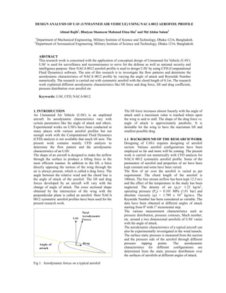
  • 1. DESIGN ANALYSIS OF UAV (UNMANNED AIR VEHICLE) USING NACA 0012 AEROFOIL PROFILE Alimul Rajib1, Bhuiyan Shameem Mahmud Ebna Hai1 and Md Abdus Salam2 1 Department of Mechanical Engineering, Military Institute of Science and Technology, Dhaka-1216, Bangladesh. 2 Department of Aeronautical Engineering, Military Institute of Science and Technology, Dhaka-1216, Bangladesh. ABSTRACT This research work is concerned with the application of conceptual design of Unmanned Air Vehicle (UAV). UAV is used for surveillance and reconnaissance to serve for the defense as well as national security and intelligence purpose. Here NACA 0012 aerofoil profile is used to design UAV by using CFD (Computational Fluid Dynamics) software. The aim of this research is to investigate the flow patterns and determine the aerodynamic characteristics of NACA 0012 profile by varying the angle of attack and Reynolds Number numerically. The research is carried out with symmetric aerofoil with the chord length of 0.1m. The research work explained different aerodynamic characteristics like lift force and drag force, lift and drag coefficient, pressure distribution over aerofoil etc Keywords: UAV, CFD, NACA 0012. The lift force increases almost linearly with the angle of 1. INTRODUCTION An Unmanned Air Vehicle (UAV) is an unpiloted attack until a maximum value is reached where upon aircraft. Its aerodynamic characteristics vary with the wing is said to stall. The shape of the drag force vs. certain parameters like the angle of attack and others. angle of attack is approximately parabolic. It is Experimental works on UAVs have been conducted in desirable for the wing to have the maximum lift and many places with various aerofoil profiles but not smallest possible drag. enough work with the Computational Fluid Dynamics (CFD) analysis is not available that much till now. The 1.1 BACKGROUND OF THE RESEARCH WORK present work contains mainly CFD analysis to Designing of UAVs requires designing of aerofoil determine the flow pattern and the aerodynamic section. Various aerofoil configurations have been characteristics of an UAV. employed so far and more will be coming. The present The shape of an aircraft is designed to make the airflow work is carried out numerically with CFD analysis for through the surface to produce a lifting force in the NACA 0012 symmetric aerofoil profile. Some of the most efficient manner. In addition to the lift, a force parameters of aerofoil and properties of air have been directly opposing the motion of the wing through the kept constant and some have been varied. air is always present, which is called a drag force. The The flow of air over the aerofoil is varied as per angle between the relative wind and the chord line is requirement. The chord length of the aerofoil is the angle of attack of the aerofoil. The lift and drag 100mm. The free stream airflow has been kept 12.5 m/s forces developed by an aircraft will vary with the and the effect of the temperature in the study has been neglected. The density of air (ρo)= 1.22 kg/m3, change of angle of attack. The cross sectional shape obtained by the intersection of the wing with the operating pressure (Po) = 0.101 MPa (1.01 bar) and absolute viscosity (μ) = 1.789 x 10⁻⁵ kg/m-s. The perpendicular plane is called an aerofoil. Here NACA 0012 symmetric aerofoil profiles have been used for the Reynolds Number has been considered as variable. The present research work. data have been obtained at different angles of attack starting from 0o with 1o incremental step. The various measurement characteristics such as pressure distribution, pressure contours, Mach number, etc. around a two dimensional aerofoils of UAV varies with the angle of attack. The aerodynamic characteristics of a typical aircraft can also be experimentally investigated in the wind tunnels. The surface static pressure is measured from the suction and the pressure side of the aerofoil through different pressure tapping points. The aerodynamic characteristics for different configurations are determined from the static pressure distribution over the surfaces of aerofoils at different angles of attack. Fig 1: Aerodynamic forces on a typical aerofoil
  • 2. 1.2 OBJECTIVES 2.2 AEROFOIL DESIGN a. Designing of NACA 0012 aerofoil section and The vertices obtained from the C program were used to investigation of the flow pattern with the help of draw the profile line which was as follows: CFD software. b. Determination of the surface static pressure distribution, pressure contours, Mach number on the aerofoils in the biplane configuration. c. Determination of the aerodynamic characteristics from the static pressure distributions. d. Discussion on the computational results of the Fig 3: NACA 0012 aerofoil section. CFD analysis. The boundary was then given. 2. WORKING PRINCIPAL The computation and graphical plotting involves the Table 1: Values of boundary vertices for NACA 0012 following sequence: aerofoil profile. a. Programming to get vertices for aerofoil section using governing equation. Label X Y Z b. Working with vertices using GAMBIT software. A 0.1 1.25 0 c. Working with FLUENT software. B 2.1 1.25 0 C 2.1 0 0 2.1 DESIGN METHOD D 2.1 -0.25 0 The early NACA aerofoil series, the 4-digit was E 0.1 -0.25 0 generated using analytical equations that describe its F -1.15 0 0 geometrical feature. G 0.1 0 0 The boundaries were chosen such to get uniform meshing. Line and face both the meshing were employed here. To mesh, interval counts and successive ratios were used here. After employing boundary and meshing the following meshed geometry was found. Fig 2: NACA aerofoil geometrical construction. The first digit specifies the maximum camber (m) in percentage of the chord, the second indicates the position of the maximum camber (p) in tenths of chord, and the last two numbers provide the maximum thickness (t) of the aerofoil in percentage of chord. So, our concerned NACA 0012 aerofoil means 0% camber at 0 (zero) position (as there is no camber) and thickness of .012m. The thickness distribution above (+) and below (-) the mean line was calculated by plugging the value of t into the following equation for each of the x coordinates.   t Fig 4: Meshing of aerofoil section (2D).  yt  x  0 . 1260 x  0 . 3516 x 2  0 . 2843 x 3  0 . 1015 x 4 0 . 2969 0 .2 It was recommended that the boundaries around the The equation was solved here by a C program to find aerofoil were far enough. vertices for the aerofoil line. Approximately, 10,000 vertices were used. 2.3 Analysis of Data in Fluent The mesh file was imported to the Fluent and it required certain features. First of all, 2-D mode was selected. The parameters which needed to be constant were: pressure (atmospheric pressure = 101325 Pa), air velocity (v = 12.5 m/s), density of air (ρ = 1.225 kg/m3), absolute viscosity (μ = 1.789 x 10⁻⁵ kg/m-s). The Reynolds number and Mach number were kept constant and sometimes varied as per requirement.
  • 3. 3. RESULTS AND GRAPHS 3.4 Angle of attack Vs Drag coefficient: 3.1 Lift coefficient (CL) Sample results of lift coefficient CL with variable angle 0.025 of attack α and Reynolds number Re are as follows: Table3. Values of CL: 0.02 Lift coefficient Re CL 0.015 α 3.6 x 10⁵ 7 x 10⁵ 1 x 10⁶ 2 x 10⁶ 5 x 10⁶ 0.01 0 0.0000 0.0000 0.0000 0.0000 0.0000 0.005 2 0.2200 0.2200 0.2200 0.2200 0.2200 0 4 0.4400 0.4400 0.4400 0.4400 0.4400 0 2 4 6 8 10 12 14 6 0.6600 0.6600 0.6600 0.6600 0.6600 Angle of attack 8 0.8542 0.8800 0.8800 0.8800 0.8800 Re = 360000 Re = 700000 Re = 1000000 10 0.9811 1.0343 1.0512 1.0727 1.1000 Re = 2000000 Re = 5000000 12 0.9132 1.0390 1.1212 1.2072 1.2673 14 - 0.6284 0.8846 1.1614 1.3423 Fig 6: Angle of attack Vs Drag coefficient for several Reynolds number (Re). 3.2 Drag coefficient (CD) Table2. Values of CD. 3.5 Pressure Distribution over NACA 0012 Aerofoil Re CD α 3.6 x 10⁵ 7 x 10⁵ 1 x 10⁶ 2 x 10⁶ 5 x 10⁶ 0 0.0079 0.0067 0.0065 0.0064 0.0064 2 0.0084 0.0070 0.0068 0.0066 0.0066 4 0.0098 0.0083 0.0078 0.0073 0.0072 6 0.0125 0.0108 0.0101 0.0090 0.0081 8 0.0153 0.0128 0.0119 0.0105 0.0092 10 0.0184 0.0159 0.0147 0.0128 0.0106 12 0.0217 0.0195 0.0180 0.0155 0.0130 14 - 0.0236 0.0222 0.0191 0.0159 These values are used to find the graphs: (a) lift coefficient vs. angle of attack and (b) drag coefficient vs. angle of attack graphs for various Reynolds number. 3.3 Lift coefficient Vs Angle of attack: Fig 7: The pressure distribution for the NACA 0012 aerofoil under free stream condition for Mach number 1.6 0.7 and angle of attack 4o. 1.4 1.2 Lift coefficient 1 0.8 0.6 0.4 0.2 0 0 5 10 15 20 Angle of attack Re = 360000 Re = 700000 Re = 1000000 Re = 2000000 Re = 5000000 Fig 5: Lift coefficient Vs Angle of attack for several Reynolds number (Re). This graph shows that maximum lift coefficient is not constant for NACA 0012 aerofoil, it increases with the increasing Reynolds number with angle of attack. Fig 8: The pressure distribution for the NACA 0012 aerofoil for inviscid flow for Mach number 0.8 and angle of attack 2o.
  • 4. 7. NOMENCLATURE Symbol Meaning Unit α Angle of attack Degree Re Reynolds number None CL Lift coefficient None CD Drag coefficient None kg/m3 ρo Density of air Po Operating pressure MPa μ Absolute viscosity kg/m-s v air velocity m/s Fig 9: The pressure distribution for the NACA 0012 aerofoil for viscid flow for Mach number 0.7 and angle of attack 4o. 4. DISCUSSION From Fig 5 it is seen that at zero degree angle of attack the lift coefficient is zero and it increases linearly with the increase of angle of attack. After reaching at a peak point, the lift coefficient decreases sharply with the increase of angle of attack and the values also vary with different Reynolds number. One major feature of drag coefficient is that for zero degree angle of attack it is not zero and so thus the drag force. From Fig 6, parabolic curves are found as were expected. 5. CONCLUSION This research work has been carried out to observe the characteristics of UAV NACA 0012. This mainly involved the conceptual design for better design and economical construction. The design concept is a better approach to choose among various types of UAV (Unmanned Air Vehicle). Mainly, this work has brought some important aerodynamic characteristics of aerofoils. These results found in two dimensional designs may vary with the three dimensional. 6. REFERENCES 1. Sq Ldr GM Jahangir Alam, 2007, “Investigation Of The Aerodynamic Characteristics Of The Biplane Configurations Using NACA 0024 Profile”, M. Sc. Thesis, BUET, Dhaka, Bangladesh. 2. J. N. Reddy, 2005, Finite Element Method, Texas A & M University, Texas. 3. Byron S. Gottfried, 1996, Schaum’s Outline Of Theory And Problems Of Programming With C 4. Rajesh Bhaskaran, Fluent Tutorials. 5. James C. Date and Stephen R. Turnock, 2002, “Computational Evaluation Of The Periodic Performance Of A NACA 0012 Fitted With A Gurney Flap”. 6. Bertin J.J, Smith M.L., “Aerodynamics for Engineers”, 3rd – Ed, Prentice Hall. 7. Clancy, L. J., “Aerodynamics”.