
Recomendados
Más contenido relacionado
La actualidad más candente
La actualidad más candente (20)
Destacado
Destacado (19)
Similar a Capacitors
Similar a Capacitors (20)
Más de amckaytghs
Último
Último (20)
Capacitors
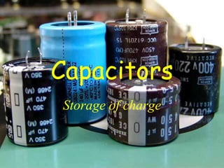
- 1. Capacitors Storage of charge
- 2. Introduction • Read Chapter 14 in ESA and then; – Write a brief description of what a capacitor is and what it does, make sure you mention dielectric – Describe the maths; capacitance, units, capacitor formula – Explain how capacitors behave in DC circuits in series and parallel
- 3. Electronic Components • Capacitors are electronic components that store charge efficiently • They can be charged and discharged very quickly and hold their charge indefinitely • Symbol
- 4. The structure of the capacitor • Capacitors are made from two parallel metal plates separated by an insulator called a dielectric • In practice they appear a little more complex
- 5. Charging a Capacitor • In a circuit the capacitor plate closest to the negative terminal of the battery or power supply is “stacked” with electrons (negative charges) • The opposite plate becomes positively charged • There is no movement of charge between the plates as they are insulated by the dielectric
- 6. Capacitance (symbol C) • Capacitance is the amount of charge a capacitor can store when connected across a potential difference of 1V (the larger the capacitance the more charge it can store) Q • Units of capacitance are Farads (symbol F) • 1 Farad = 1 coulomb per volt This is a lot of charge!! • most capacitors are small; μF (1 x 10⁻⁶ F) nF (1 x 10⁻⁹ F) pF (1 x 10-12 F) V C Where; C=Capacitance in Farads (F) Q=Charge in Coulombs (C) V=Voltage in Volts(V)
- 7. Exercises 1. Calculate the capacitance of a capacitor that stores 1.584 10-9 C at 7.2V 220 μF 2. A 330μF capacitor is charged by a 9.0V battery. How much charge will it store? 2.97 10-3 C 3. A 0.1μF capacitor stores 1.5 10-7 C of the charge. What was the voltage used to charge it? 1.5V
- 8. Capacitance (C) Three factors determine capacitance; 1. The area of the plates (CA) 2. The distance separating the plates 1 (C ) d 3. The properties of the dielectric (εr) so C= constant x A d
- 9. Capacitor Construction Formula • If there is air or a vacuum between the plates the constant is; the absolute permittivity of free space (symbol ε0) (ε0 = 8.84 x 10⁻¹² Fm-1) so; A C 0 d
- 10. Exercises C 0 Using the absolute permittivity of free space (ε0 = 8.84 10-12 Fm-1) A 1. Calculate the capacitance of a capacitor that has a plate separation of 15 microns (μm) and measures 45cm by 28cm. 74nF 2. A 1000 μF has an area of 2cm by 4.8m. What is the distance between the plates in mm? 8.48 10-7mm 3. A 0.3 μF capacitor with a plate separation of 2 microns. What is the area of the capacitor? 0.68m2 d
- 11. Capacitor Construction Formula • When an insulator (dielectric) is placed between the plates the capacitance increases • The dielectric constant (symbol εr) gives the proportion by which the capacitance will increase so; and therefore dielectic r air C C C r o d A Note that εr has no units as dielectric air C r C Insulator εr Air 1 Polystyrene 2.5 Glass 6.0 Water 80
- 12. The Role of the Dielectric • Charge separation in a parallel-plate capacitor causes an internal electric field. A dielectric (orange) increases the field strength and increases the capacitance
- 13. Examples 1. Calculate the capacitance of a capacitor with a polystyrene dielectric (εr =2.5), an area of 1.2cm by 3.2m and a plate separation of 8 microns 1.06 10-7 F 2. Calculate the plate area required for a 1000 μF, glass (εr=6.0) capacitor, with a plate separation of 2.8 micrometres. 53m2 3. Calculate the dielectic constant of a 10000 μF capacitor with a 1.2μm plate separation and an area of 16.97m2 80 d A C r o (ε0 = 8.84 x 10⁻¹² Fm- 1)
- 14. Networks of Capacitors Capacitors in Parallel • For two or more capacitors in parallel the capacitance is 1 2... C C C parallel • Each capacitor has the same voltage charging it so; The more capacitors in parallel circuit the greater the capacitance of the circuit
- 15. Capacitors in Series • Capacitors share the supply voltage • The inner plates are an isolated circuit where the existing charges are just rearranged so; ... 1 1 1 1 2 C C C series The more capacitors in series the less the total capacitance of the circuit
- 16. Examples 1. A circuit has three 330 μF capacitors in series. Calculate the total capacitance of the circuit 110 μF 2. Another circuit has three 330 μF capacitors in parallel. Calculate the total capacitance of the circuit. 990 μF 3. Briefly explain why these two circuits have a different total capacitance. The parallel capacitors are each charged separately while the series capacitors charge through one another, effectively just rearranging the charges within each capacitor (the electric field is weakened by the addition of each capacitor in series)
- 17. Energy Stored in Capacitors • The graph of voltage against charge for a cell is a horizontal line – The energy provided by the cell is equal to the area under the line • The graph of voltage against charge is a straight line through (0, 0) – The energy stored in a capacitor is; 1 E QV P 2 Q V Energy Produced by a Cell Energy Stored by a Capacitor Q V
- 18. Energy Stored in Capacitors 1 • Energy of a capacitor can also be given by; (because Q=CV) or Q (because ) E QV P 2 1 2 E CV P 2 Q C EP 2 1 2 C V Energy is stored as electrical charge on the plates of a capacitor
- 19. Exercises 1 E CV 2 P 1. Calculate the energy stored in a 330μF capacitor charged by a 24V supply. 0.095J 2. Calculate the capacitance of a capacitor that stores 1.8 10-3 J of energy at 18V 11 μF 3. Calculate the voltage require to store 0.1J of energy on a 1000μF capacitor 200V 2
- 20. Charging and Discharging Capacitors 1. Charging a Capacitor • As a capacitor charges the voltage increases to the supply voltage (exponential growth curve) • and the current decreases as the plates become “full” of charge (exponential decay curve) Current Time Voltage Supply voltage Time The shape of these curves can be controlled by a resistor in series, the higher the resistance the slower the charge
- 21. Charging and Discharging Capacitors 2. Discharging a Capacitor • The voltage across the plates of the capacitor drops as the charges flow away from the plate • The current decreases as there are fewer charges on the plates repelling each other Current Time Voltage Time The shape of these curves can be controlled by a resistor in series, the higher the resistance the slower the discharge
- 22. Time Constant ( ) • The time constant ( )is a measure of how quickly a capacitor charges or discharges – This will depend on: • The resistance (R) of the circuit (how much current flows) • The capacitance (C) of the capacitor (how much charge is stored) so: RC NB; one time constant is not the total time to charge or discharge but the time to discharge to 37.5% or to charge to 63.5% of the total
- 23. Time Constant ( ) • One time constant is not the total time to charge or discharge but the time to discharge to 37.5% or to charge to 63.5% of the total • Experts; this is because of the exponential nature of the charge/discharge curves V RC t 63.5 % V t RC 37. 5% C For Decay V V e when t V V e 1 1 C t C as e 0.37, V 0.37 V , , ( ) C For growth V V 1 e when t V V 1 e 1 1 C t C as e 0.37, V 0.63 V ( )
- 24. Examples 1. Calculate the time constant for 330μF capacitor in a 20 charging circuit 6.6 10-3s 2. Calculate the time constant for 330μF capacitor in a 15 discharging circuit 5.0 10-3s 3. Calculate the amount of charge on each of the capacitors in 1 and 2 after 1 time constant when charged from 12V supply. 1 = 2.5 10-3C, 2=1.5 10-3C
- 25. Exercises • Try ESA, Activity 14A,B,C, Pg 224 • ABA, Pg 139-153