4. Objectives
Recognize what is heat exchanger
Differentiate numerous types of heat exchanger, their
classification and their applications
Know the heat transfer equipment terminologies
Know the primary consideration in the selection of
heat exchangers
5. What is a heat transfer equipment?
An equipment that permits efficient transfer of heat
from a hot fluid to a cold fluid without any or with
direct contact of fluids
Such an equipment is called
Heat Exchanger
6. What is a Heat Exchanger?
Technically speaking ……
A heat exchanger is a device that is used to
transfer thermal energy (enthalpy) between
two or more fluids, between a solid surface and
a fluid,
or between solid particulates and a fluid,
at different temperatures
and in thermal contact.
7. Heat Exchanger
Heat exchangers, can be seen in daily life, like ??
as well as in industries, like??
What are these?
8. Aim and Application of HE
Typical applications involve heating or cooling of a
fluid stream of concern and evaporation or
condensation of single- or multicomponent fluid
streams.
In other applications, the objective may be to recover
or reject heat, or sterilize, pasteurize, fractionate,
distill, concentrate, crystallize, or control a process
fluid.
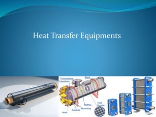
Common examples of heat exchangers are shell-and
tube exchangers, automobile radiators, condensers,
evaporators, air preheaters, and cooling towers.
9. Aim and Application of HE
There could be internal thermal energy sources in
the exchangers, such as in electric heaters and
nuclear fuel elements.
Combustion and chemical reaction may take place
within the exchanger, such as in boilers, fired
heaters, and fluidized-bed exchangers.
Mechanical devices may be used in some
exchangers such as in scraped surface exchangers,
agitated vessels, and stirred tank reactors.
10. Aim and Application of HE
Heat exchanger found applications in almost all
Chemical and petrochemical plants
Air Conditioning Systems
Power production
Waste Heat recovery
Automobile Radiator
Central Heating System
Electronic Parts
11. Different Terminologies of Heat
Transfer Equipment
Heat exchanger: both sides single-phase and process streams
Cooler: one stream a process fluid and the other cooling water
or air.
Heater: one stream a process fluid and the other a hot utility,
such as steam or hot oil.
Condenser: one stream a condensing vapor and the other
cooling water or air.
Chiller: one stream a process fluid being condensed at sub-
atmospheric temperatures and the other a boiling refrigerant or
process stream.
Reboiler: one stream a bottoms stream from a distillation
column and the other a hot utility (steam or hot oil) or a process
stream.
12. Different Terminologies of Heat
Transfer Equipment
Discuss and elaborate the examples in
daily life and/or industrial process of
each of the above mentioned
equipments
13. Heat Exchanger Classification
Heat exchangers are classified according to
Transfer process
Number of fluids
Degree of surface compactness
Construction
Flow arrangements
Heat transfer mechanisms
17. Classification by Transfer Processes
1. Indirect contact type
The fluid streams remain separate and the
heat transfers continuously through a dividing
wall into and out of the wall in a transient
manner.
18. Classification by Transfer Processes
1. Indirect contact type
a) Direct transfer type heat exchanger
b) Storage type heat exchanger
c) Fluidized bed heat exchanger
19. Classification by Transfer Processes
a) Direct Transfer Type Heat Exchanger
In this, type heat transfers continuously from the hot fluid to
the cold fluid through a dividing wall.
There is no direct mixing of the fluids because each fluid
flows in separate fluid passages.
It is also known as recuperator. Examples, tubular
exchangers, plate and frame heat exchangers and extended
surface exchangers.
Tubular Exchanger Plate and Frame Exchanger
20. Classification by Transfer Processes
b) Storage Type Heat Exchanger (Regenerative Heat
Exchanger)
In a storage type exchanger, both fluids flow alternatively through
the same flow passages, and hence heat transfer is intermittent.
The heat transfer surface (or flow passages) is generally cellular in
structure and is referred to as a matrix, or it is a permeable (porous)
solid material, referred to as a packed bed.
When hot gas flows over the heat transfer surface (through flow
passages), the thermal energy from the hot gas is stored in the
matrix wall, and thus the hot gas is being cooled during the matrix
heating period.
As cold gas flows through the same passages later (i.e., during the
matrix cooling period), the matrix wall gives up thermal energy,
which is absorbed by the cold fluid.
Thus, heat is not transferred continuously through the wall as in a
direct-transfer type exchanger (recuperator), but the corresponding
thermal energy is alternately stored and released by the matrix wall.
21. Classification by Transfer Processes
b) Storage Type Heat Exchanger (Regenerative Heat
Exchanger)
Fixed Bed Regenerator
Continuous-passage matrices for a rotary regenerator:
(a) notched plate; (b) triangular passage.
22. Classification by Transfer Processes
b) Storage Type Heat Exchanger (Regenerative
Heat Exchanger)
Regenerative heating was one of the most important
technologies developed during the Industrial Revolution
when it was used in the hot blast process on blast
furnaces.
It was later used in glass and steel making, to increase
the efficiency of open hearth furnaces, and in high
pressure boilers and chemical and other applications,
where it continues to be important today.
23. Classification by Transfer Processes
c) Fluidized bed heat exchanger
In a fluidized-bed heat
exchanger, one side of a two-
fluid exchanger is immersed in a
bed of finely divided solid
material, such as a tube bundle
immersed in a bed of sand or
coal particles.
The common applications of the
fluidized-bed heat exchanger are
drying, mixing, adsorption,
reactor engineering, coal
combustion, and waste heat
recovery
24. Classification by Transfer Processes
2. Direct-Contact Heat Exchanger
In a direct-contact exchanger, two fluid streams come
into direct contact, exchange heat, and are then
separated.
Common applications of a direct-contact exchanger
involve mass transfer in addition to heat transfer, such
as in evaporative cooling and rectification.
However, the applications are limited to those cases
where a direct contact of two fluid streams is
permissible.
25. Classification by Transfer Processes
2. Direct-Contact Heat Exchanger
a) Immiscible Fluid Exchangers
b) Gas–Liquid Exchangers
c) Liquid–Vapor Exchangers
26. Classification by Transfer Processes
a) Immiscible Fluid Exchangers
In this type, two immiscible fluid streams are brought into
direct contact.
These fluids may be single-phase fluids, or they may involve
condensation or vaporization.
Condensation of organic vapors and oil vapors with water or
air are typical examples.
27. Classification by Transfer Processes
b) Gas–Liquid Exchangers
In this type, one fluid is a gas (more commonly, air) and
the other a low-pressure liquid (more commonly, water)
and are readily separable after the energy exchange.
In either cooling of liquid (water) or humidification of gas
(air) applications, liquid partially evaporates and the vapor
is carried away with the gas.
In these exchangers, more than 90% of the energy transfer
is by virtue of mass transfer (due to the evaporation of the
liquid), and convective heat transfer is a minor mechanism.
A ‘‘wet’’ (water) cooling tower with forced- or natural-draft
airflow is the most common application.
Other applications are the air-conditioning spray chamber,
spray drier, spray tower, and spray pond.
28. Classification by Transfer Processes
c) Liquid–Vapor Exchangers
In this type, typically steam is partially or fully
condensed using cooling water, or water is heated with
waste steam through direct contact in the exchanger.
Noncondensables and residual steam and hot water are
the outlet streams.
Common examples are desuperheaters and open
feedwater heaters (also known as deaerators) in power
plants.
29. Classification by Transfer Processes
2. Direct-Contact Heat Exchanger
Compared to indirect contact recuperators and
regenerators, in direct-contact heat exchangers,
(1) very high heat transfer rates are achievable,
(2) the exchanger construction is relatively
inexpensive, and
(3) the fouling problem is generally nonexistent,
due to the absence of a heat transfer surface
(wall) between the two fluids.
31. Classification by Number of Fluid
Most processes of heating, cooling, heat recovery, and heat
rejection involve transfer of heat between two fluids.
Hence, two-fluid heat exchangers are the most common.
Three fluid heat exchangers are widely used in cryogenics
and some chemical processes (e.g., air separation systems,
a helium–air separation unit, purification and liquefaction
of hydrogen, ammonia gas synthesis).
Heat exchangers with as many as 12 fluid streams have
been used in some chemical process applications.
33. Classification by Surface Compactness β
Heat exchangers are characterized by a large heat
transfer surface area per unit volume of the exchanger,
resulting in
reduced space,
reduce weight,
reduce support structure and footprint,
energy requirements and cost,
as well as improved process design
and plant layout and processing conditions, together
with low fluid inventory.
34. Classification by Surface Compactness β
The ratio of the heat transfer surface area of a
heat exchanger to its volume is called the area
density or surface compactness β.
A heat exchanger with β = 700 m2/m3 (or 200
ft2/ft3) is classified as being compact. Examples
of compact heat exchangers are car radiators (
1000 m2/m3) and the human lung ( 20,000
m2/m3).
36. Classification by Heat Transfer Mechanisms
The basic heat transfer mechanisms employed for transfer
of thermal energy from the fluid on one side of the
exchanger to the wall (separating the fluid on the other
side) are
single-phase convection (forced or free),
two-phase convection (condensation or evaporation, by
forced or free convection),
and combined convection and radiation heat transfer.
Any of these mechanisms individually or in combination
could be active on each fluid side of the exchanger.
Some examples of each classification type are automotive
radiators, passenger space heaters, regenerators,
intercoolers, economizers and so on.
39. Classification by Flow Arrangement
The choice of a particular flow arrangement is
dependent on the required exchanger
effectiveness,
available pressure drops,
minimum and maximum velocities allowed,
fluid flow paths,
packaging envelope,
allowable thermal stresses,
temperature levels,
piping and plumbing considerations,
and other design criteria.
40. Classification by Flow Arrangement
Single Pass flow arrangement
A fluid is considered to have made one pass
if it flows through a section of the heat
exchanger through its full length.
a) Counterflow exchanger
• In a counterflow or countercurrent exchanger, the two fluids flow
parallel to each other but in opposite directions within the core.
• The counterflow arrangement is thermodynamically superior to any
other flow arrangement.
• It is the most efficient flow arrangement, producing the highest
temperature change in each fluid compared to any other two-fluid
flow arrangements for a given overall thermal conductance (UA),
fluid flow rates and fluid inlet temperatures.
• The maximum temperature difference across the exchanger produces
minimum thermal stresses in the wall for an equivalent performance
compared to any other flow arrangements.
41. Classification by Flow Arrangement
Single Pass flow arrangement
b) Parallelflow exchanger
• In a parallelflow (also referred to as cocurrent or
cocurrent parallel stream) exchanger, the fluid
streams enter together at one end, flow parallel
to each other in the same direction, and leave
together at the other end.
• This arrangement has the lowest exchanger
effectiveness among single-pass exchangers for
given overall thermal conductance and fluid
flow rates and fluid inlet temperatures.
• In a parallelflow exchanger, a large temperature
difference between inlet temperatures of hot
and cold fluids exists at the inlet side, which
may induce high thermal stresses in the
exchanger wall at the inlet.
42. Classification by Flow Arrangement
Single Pass flow arrangement
c) Crossflow Exchanger
• In this type of exchanger, the two fluids flow in
directions normal to each other.
• Thermodynamically, the effectiveness for the
crossflow exchanger falls in between that for the
counterflow and parallel flow arrangements.
• The largest structural temperature difference
exists at the ‘‘corner’’ of the entering hot and
cold fluids.
• This is one of the most common flow
arrangements used for extended surface heat
exchangers, because it greatly simplifies the
header design at the entrance and exit of each
fluid.
43. Classification by Flow Arrangement
Single Pass flow arrangement
c) Splitflow Exchanger
• In this exchanger, the shell fluid stream enters at the center of the
exchanger and divides into two streams.
• These streams flow in longitudinal directions along the exchanger length
over a longitudinal baffle, make a 180° turn at each end, flow
longitudinally to the center of the exchanger under the longitudinal baffle,
unite at the center, and leave from the central nozzle.
• The other fluid stream flows straight in the tubes.
44. Classification by Flow Arrangement
Multipass flow arrangement
After flowing through one full length, if the flow
direction is reversed and fluid flows through an
equal- or different-sized section, it is considered to
have made a second pass (or multipass) of equal or
different size.
45. Take Home Assignment
What are the types, examples and applications of the
Multipass Flow Exchangers?
53. Types of Heat Exchangers
We will study industrially important
heat exchanger in more detail in
upcoming lectures
54. Approach to Heat-Exchanger Design
The proper use of basic heat-transfer knowledge in
the design of practical heat-transfer equipment is an
Art
Designers must be constantly aware of the differences
between the idealized conditions for, and under which
the basic knowledge was obtained and the real
conditions of the mechanical expression of their
design and its environment.
55. Approach to Heat-Exchanger Design
The H.E design must satisfy process and operational
requirements (such as availability, flexibility, and
maintainability) and do so economically.
An important part of any design process is to consider
and offset the consequences of error
in the basic knowledge of heat transfer,
in its subsequent integration into a design method,
in the translation of design into equipment,
in the operation of the equipment and the process.
Heat-exchanger design is not a highly accurate art
under the best of conditions.
56. Selection criterion for heat exchangers
1. Material of construction
2. Operating temperatures and pressures conditions
3. Flow rates
4. Flow arrangements
5. Performance parameters such as thermal effectiveness and
pressure drops
6. Fouling tendencies
7. Types and phases of fluid
8. Maintenance, inspection, cleaning ,extension and repair
possibilities
9. Overall economy
10. Fabrication techniques
57. 1. Material of construction
For reliable and continuous use,
the material of construction of heat exchangers should
have well defined corrosion rate in service
environment.
the material should exhibit strength to with stand with
operating and temperature and pressure
58. 2. Operating temperature and pressure conditions
Pressure
The design pressure is important to determine the thickness of pressure
retaining components. The higher the pressure, the greater will be the
required thickness of pressure retaining equipment.
Temperature
Design temperature: This parameter is important as it indicate whether a
material at design temperature can withstand the operating pressure and
various load imposed on component.
Shell and tube heat exchanger units can be designed for almost all condition of
temperature and pressure. In extreme cases, high pressure may impose a
limitation by fabrication problems associate with material thickness.
Compact Heat exchanger: Compact Heat exchanger are constructed from
thinner material by mechanical bonding like welding. Therefore they are limited
in operating pressure and temperature
Gasketed plate heat exchanger and spiral exchanger: these exchanger are
limited in pressure and temperature. Wherein the limitation are imposed by the
capability of gaskets
59. 3. Flow rate
Flow rate determine the flow area: the higher the
flow rate the higher will be cross flow area
60. 4. Flow arrangement
The choice of typical flow arrangement (cocurrent
or countercurrent) is dependent of required
exchanger effectiveness, exchanger construction
types.
61. 5. Performance Parameter
Thermal effectiveness
Heat exchanger effectiveness is defined as the ratio of the
actual amount of heat transferred to the maximum possible
amount of heat that could be transferred with an infinite
area.
Pressure drop
Pressure drop is an important parameter in heat
exchanger design. The heat exchanger should be design
in such a way that unproductive pressure drop should be
avoided to maximum extent in area like inlet and outlet
bends ,nozzles and manifolds
62. 6. Fouling Tendencies
Fouling is defined as formation on heat exchanger surface of
undesirable deposit that decrease the heat transfer and
increase the resistance to fluid flow, resulting in high
pressure drop. The growth of those deposit decrease the
performance of exchanger with time.
63. 7. Type and Phases of fluid
The phase of fluid within the unit is an important
consideration in selection of heat exchanger type.
Various combination of fluid dealt in exchanger are
Liquid-Liquid, Liquid-Gas and Gas-Gas
64. 8. Maintenance, inspection, cleaning,
extension and repair possibilities
The suitability of various heat exchanger depend
upon it maintenance cleaning and repairing
maintenance
Repairing and maintenance of shell and tube
exchanger is relatively easy but repairing of
expansion joint is somehow difficult.
Repairing and maintenance of compact heat
exchanger of tube/plate fin type heat exchanger is
very difficult except by plugging of tube.
65. 9. Overall Economy
There are two major cost to consider in designing of
heat exchanger,
the manufacturing cost and
operating cost, including maintenance cost
In general the less heat transfer area the less is the
complexity of design, the lower in manufacturing cost.
The operating cost is pumping cost due to pumping
device such as pumps, fans and blowers.
The maintenance cost include cost of spares that
require frequent renewal due to fouling and corrosion
66. 10. Fabrication technique
Fabrication technique is also determining factor
for heat exchanger design.
For example shell and tube exchanger mostly
fabricated by welding, plate fin heat exchanger
and automobile aluminum radiator by brazing.
Most of circular tube fin exchanger fabricate by
mechanical assembling.
67. Study Reference Materials
Fundamentals of Heat Exchanger Design. Ramesh K.
Shah and Dušan P. Sekulic, John Wiley & Sons, Inc.
Heat Exchanger Design Handbook. Kuppan
Thulukkanam, CRC Press.
Editor's Notes
Heat Exchanger Equipement in daily life such as household refrigerator or air conditioner