PLC Basic
•Descargar como PPT, PDF•
212 recomendaciones•127,029 vistas

This document provides an overview of programmable logic controllers (PLCs). It describes the basic components of a PLC including the central processing unit, input and output modules, power supply, and programming software. PLCs were developed to provide flexibility compared to traditional hardwired control systems. The document discusses PLC applications, advantages such as ease of programming and modification, as well as some disadvantages like proprietary aspects. It also covers PLC size, history, and leading manufacturers.

Recomendados
Más contenido relacionado
La actualidad más candente
La actualidad más candente (20)
Similar a PLC Basic
Similar a PLC Basic (20)
Último
Último (20)
PLC Basic
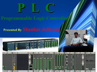
- 1. P L C Programmable Logic Controller Presented By Shankar Jothyraj
- 2. Contents What is PLC? Basic Components of a PLC PLC Advantages & Definition of PLC Central Processing Unit What is Control? CPU Duties PLC Applications History of PLC Input Modules PLC Size Need for PLC Output Modules Leading Brands of PLC Hardwire System and PLC Digital and Analog Modules Comparison Chassis and Backplane PLC Function Power Supply PLC Operating Cycle Programming Software Disadvantages
- 3. What is a PLC? The Basic Block CPU Inputs Outputs A PROGRAMMABLE LOGIC CONTROLLER is a solid state control system that continuously monitors the status of devices connected as inputs. Based upon a user written program, stored in memory, it controls the status of devices connected as outputs.
- 4. Definition of PLC • A digital electronic device that uses a programmable memory to store instructions and to implement specific functions such as logic, sequence, timing, counting and arithmetic to control machines and process. • It uses a programmable memory to store the instructions and specific functions that include On/Off control, timing counting, sequencing, arithmetic and data handling. • A PLC is a computer designed to work in an industrial environment.
- 5. What is Control? “ CONTROL is the process in a system in which one or several input variables influence other variables. “ A Simple View of a Control System INFORMATION COMMANDS C O N T R O L S Y S T E M SENSORS ACTUATORS P L A N T
- 6. History of PLC • During the late 1960s, General Motors (USA) was interested in the computer application to replace the hardwire systems. • Bedford Associates (Modicon) and Allen Bradley responded to General Motors. • The name given was “Programmable Controllers” or PC. • Programmable Logic Controller or PLC was a registered trademark of the Allen Bradley. • Later, PC was used for “Personal Computer” and to avoid
- 7. Need for PLC Hardwired panels were very time consuming to time, debug and change. The following requirements for computer controllers to replace hardwired panels. 1.Solid-state not mechanical. 2.Easy to modify input and output devices. 3.Easily programmed and maintained by plant electricians. 4.Be able to function in an industrial environment.
- 8. Hardwire System and PLC L 24 VDC S1 S2 S1 K1 K1 S2 PLC K1 N 0V Hardwire PLC
- 9. Comparison Hardwired control systems • The functions are determined by the physical wiring. • Changing the function means changing the wiring. • Can be contact-making type (relays, contactors) or electronic type (logic circuits) PLC Systems • The functions are determined by a program stored in the memory. • The control functions can be changed simply by changing the program. • Consist of a control device, to which all the sensors and actuators are connected.
- 10. PLC Function Communications Port I n p u t High Voltage Isolation Barrier C i r c u i t s Central Processor Unit (CPU) MEMORY data program Low Voltage AC Power Supply or O u t p u t C i r c u i t s Isolation Barrier CR High Voltage
- 11. PLC Operating Cycle • Four Steps in the PLC Operations START • Input Scan • Scan the state of the Inputs • Program Scan • Processes the program logic Housekeeping Input Scan Output Scan • Output Scan • Energize/de-energize the outputs • Housekeeping • This step includes communications, Internal Diagnostics, etc. • The steps are continually repeated - processed in a loop. Program Scan
- 12. How Does a PLC Work? The sensors are connected to the INPUT MODULES The processor in the CPU MODULE executes the program and scans the individual input for presence or absence of voltage 24 VDC Depending on the state of the inputs, the processor directs the OUTPUT MODULES to switch Sensors voltages Program Memory Processor Input modules Power The ACTUATORS or ANNUNCIATORS are switched “ON” or “OFF” according to the voltage Supply Output modules states Actuators / Annunciators GND
- 13. PLC Signal Flow Input Module Processor Memory Output Modules Data Output Input Image Table Image Table I:0/6 I:0/6 O:0/7 O:0/7 I:1/4 O:1/5 Input Devices Output Devices Ladder Program I:0/6 I:1/4 O:0/7 I:1/4 O:1/5 Programming Terminal O:1/5
- 14. Ladder Diagram Very similar to traditional circuit diagrams, but the current paths are arranged horizontally instead of LAD - Ladder Diagram vertically. I 0.0 I 0.1 Q 4.0 ( )
- 15. Ladder Program O:4 L1 CONTACTOR L2 L1 L2 0 CONTACTOR N.O C L2 L1 FIELD WIRING OUTPUT MODULE WIRING MOTOR •SOLENOID •VALVES •LAMP •BUZZER
- 16. Basic Components of a PLC There are five basic components in a PLC system: 1. The PLC processor, or CPU. 2. I/O (Input /Output) modules. 3. Chassis and backplane. 4. Programming software that runs in a PC. 5. Power supply.
- 17. Central Processing Unit What is CPU? The “Brain” of a PLC. Controlled by a program called the executive or operating system (OS). The executive is a collection of supervisory programs permanently stored in memory. Four basic types of CPU operations:
- 18. CPU Duties • The CPU reads in input signal states, processes the control program and controls the outputs. • The CPU provides internal Memory, timers and counters. • Stores the control program and data in its memory. • Executes the control program. • Commands connected outputs to change state based on program execution For example: Turn a light on, start a fan, adjust a speed, or temperature.
- 19. Input Modules Input modules interface directly to devices such as switches and temperature sensors. Input modules convert many different types of electrical signals such as 120VAC, 24VDC, or 4-20mA, to signals which the controller can understand.
- 20. Output Modules Output modules take a signal from a PLC and convert it to a signal that a field device needs to operate. Since there are different types of output devices, there is a wide variety of output cards available, including both digital and analog cards.
- 21. Digital/Analog Modules • Digital input modules adapt digital signals e.g. from proximity sensors. • Digital output modules convert the internal signal level of PLC into digital process signals e.g. relays. • Analog input modules adapt analog process signals e.g. from transducers. • Analog output modules convert internal digital values of the PLC to analog process signals e.g. temperature controller.
- 22. Digital and Analog Digital modules use only a single bit to represent the state of the device. For example, a switch is either open or closed. Therefore, the bit is either a 0 (switch is open) or a 1 (switch is closed). Analog modules use words to represent the state of a device. An analog signal represents a value.. For example, the temperature could be 5, 9, 20, 100, etc degrees. Analog modules use a value, such as 52, rather than a 0 or 1 to represent the state of the device.
- 24. What are Inputs? • Switches and Pushbuttons • Sensing Devices • Limit Switches • Photoelectric Sensors • Proximity Sensors • Condition Sensors • Pressure Switches • Level Switches • Temperature Switches • Vacuum Switches • Float Switches • Encoders
- 25. What are Outputs? • Valves • Motor Starters • Solenoids • Actuators • Control Relays • Horns & Alarms • Stack Lights • Fans • Counter • Pumps • Printers
- 26. Chassis and Backplane All PLCs need some method of communicating between the controller, I/O and communications modules. Here are three ways used to accomplish this communications between the various components that make up the PLC system.
- 27. Power Supply A power supply is needed to provide power to the PLC and any other modules. Power supplies come in various forms: • Power supply modules that fit into one of the slots in a chassis •External power supplies that mount to the outside of a chassis •Stand alone power supplies that connect to the PLC or I/O through a power cable •Embedded power supplies that come as part of the PLC block.
- 28. Programming Software Software that runs on a PC is required to configure and program PLCs Different products may require different programming software. Software allows programs to be written in several different languages.
- 29. Types of Programme Memory Program memory Programmable (Read-write memory) Non-programmable Alterable UV erasable EPROM / REPROM Semiconductor RAM Non-alterable ROM / PROM Electrically erasable EEPROM / EAPROM Semiconductor EEPROM / EAPROM
- 30. PLC Requirements List of items required when working with PLCs: 1. Programming Terminal - laptop or desktop PC. 2. PLC Software. PLC manufacturers have their own specific software and license key. 3. Communication cable for connection from Laptop to PLC. 4. Backup copy of the ladder program (on diskette, CDROM, hard disk, flash memory). If none, upload it from the PLC. 5. Documentation- (PLC manual, Software manual, drawings, ladder program printout, and Seq. of Operations manual.)
- 32. PLC Relay
- 33. Simple PLC network digital inputs analog inputs / outputs digital outputs
- 34. PLC Advantages •Handles much more complicated systems. •Less and simple wiring. •Increased Reliability. •More Flexibility. •Lower Cost . •Faster Response. •Easier to troubleshoot. •Remote control capability. •Communication Capability.
- 35. PLC Disadvantages •In contrast to microcontroller systems that have what is called an open architecture, most PLCs manufacturers offer only closed architectures for their products . •PLC devices are proprietary, which means that parts and software from one manufacturer can ‘t easily be used in combination with parts of another manufacturer, which limits the design and cost options. •PLC were Designed for Relay Logic Ladder and have Difficulty with some Smart Devices. •To maximize PLC performance and Flexibility, a number of Optional Modules must be added
- 36. PLC Applications • Originally hardwired arrays of relays were used to control the operation of heavy machines that contain motors and other high power devices. • PLCs were originally used to substitute the switching relay networks used in industrial applications, but now they can also be used implement other tasks such as timing, delaying counting, calculating, comparing and processing of analog signals.
- 37. PLC Size 1. SMALL - It covers units with up to128 I/O’s and memories up to2 Kbytes. - These PLC’s are capable of providing simple to advance levels or machine controls. 2. MEDIUM- Have up to 2048 I/O’s and memories up to 32 Kbytes. 3. LARGE - The most sophisticated units of the PLC family. They have up to 8192 I/O’s and memories up to 750 Kbytes. - Can control individual production processes or entire plant.
- 38. Leading Brands of PLC AMERICAN: Allen Bradley Gould Modicon Texas Instruments General Electric Westinghouse Cutter Hammer Square D EUROPEAN: Siemens Klockner & Mouller