SlideShare una empresa de Scribd logo
1 de 15
1.18 Line Integral of Electric Field: -It is the basic property of electrostatic field.
dl
r
r
EV
B
A
.∫−= “The negative of the line integral
of electric field between any two points is equal to the
potential difference”.
Proof:-Consider a point charge +q placed at origin O of
the coordinate system. A small test charge qo is moving
from A to B along a curved path. At any point P where
OP = r, electric field intensity is E, so force on test
charge qo is qo E directed radially outward from +q.
To prevent acceleration of the test charge due to this
force, an external force F = − q0 E has to be applied. If test charge is displaced from P to Q such that PQ = dl . Then
work done by the external force.
Total work done by external force in moving from A to B is ∫ •−=∫=
→→B
A
AB
r
r
ldEq
r
r
dWW
B
A
0
∫−=−−−−−•∫−=
B
A
B
A
r
r
dlE
q
W
dl
r
r
E
q
W
So ABAB
θcos)1(
00
θθ
πε
coscos
4
1
2
0
dldr
dl
dr
PQ
PN
PNQinBut
r
q
EfieldelectricBut =⇒==∆=
∫−=
B
A
r
r
dr
r
q
q
W
isechunitperBtoAfrommovinginforceexternalbydoneworktotalHence AB
2
00 4
1
arg
πε
⇒∫−= −
B
A
r
r
drr
q
q
WAB 2
00 4πε












−
−=
+−
−=
−+−
14124
1
0
12
00
rqrq
q
W B
A
B
A
AB
r
r
r
r πεπε








−== 





AB
rr
q
r
q
q
W B
A
AB
r
r
11
4
1
4 0
1
00 πεπε
.
So potential between two point A & B
V = dl
r
r
E
B
A
.∫− = 







−
AB
rr
q 11
4 0πε
1.19 Potential Difference: -Work done in moving a unit
positive charge from one point to another point in electric field
is defined as potential difference (V). It is a scalar quantity &
its SI unit is Volt.
V = VB −VA =
0
AB
q
W
= Volt1
Coulomb1
Joul1
= If work done in moving a one coulomb
positive charge from one point to another point in the electric field is 1 Joule then potential difference of the points
is 1 Volt.
1. 20 Electrostatic Force is Conservative Force: -Let +q is a charge at O then work done in moving a test
charge from A to B along Path L1 is








−=∫−=
→→
AB
rr
q
ld
r
r
E
q
W B
A
AB 11
4
.
00 πε
- - -(1)
Work done in moving the test charge from B to A along L2 path is
0
BA
q
W
=
→→
∫− ld
r
r
E
A
B
. = 







−
BA
rr
q 11
4 0πε --
(2)
Total work done in moving the test charge over close path AL1BL2A is
000 q
W
q
W
q
W BAABABA
+=
2&1 eqeqFrom 0
1111
4 00
=
















−+








−=
ABBA
rrrr
q
q
WABA
πε
0.
0
=−= ∫ dl
c
E
q
WABA
The line integral of electric field along the closed path in electrostatic field is zero.
Hence work done in moving a test charge along a closed path is zero ie work done is independent of the path. So
electrostatic force is conservative force.
1.21Potential:- Work done in bringing a unit positive charge from infinite to any point in electric field is define as
potential of the point(V). It is a scalar quantity & its SI unit is Volt. V =
0q
W A∞
V =
0
ABA
q
W
= Volt1
Coulomb1
Joul1
=
If work done in moving a one coulomb positive charge from infinite to any point in the electric field is 1 Joule then
potential of the point is 1 Volt. In c.g.s. System, unit of potential is stat volt. 1 stat volt = 300 volt.
If work done in moving a one stat coulomb positive charge from one point to another point in the electric field is 1
erg then potential difference of the points is 1 Stat Volt.
Electric potential of a point is equal to negative of the line integral of the electric field intensity from infinite to the
points. In this case A
r = ∞ , r B
= r . V = ∫
∞
→→
−
r
dl.E
r
q
V
r
q
V
00 4
111
4 πεπε
=⇒





∞
−=
1.21Potential due to a Point Charge: -Consider a point charge +q at O. OB = r . We have to find field
intensity at point B. At point A electric field intensity )1(
4
1
2
0
−−−=
x
q
E
πε
Along OA
Work done in bringing a unit positive charge from A to C is dW = F . dx But F = − q0 E
isBintpoofpotentialSodxE
r
q
r
dWBW 0∫∫
∞
−=
∞
=∞ ∫
−
==
∞
∞
r
B
dx
x
q
q
W
V 2
00 4
1
πε
⇒∫−= −
Br
Ar
dxx
q
V 2
04πε
( ) rr
r
x
q
V
xqxq
V
∞
−
∞
+−
∞






=⇒
−
−=
+−
−= 



 1
414124 0
1
0
12
0 πεπεπε
r
q
V
r
q
V
00 4
111
4 πεπε
=⇒





∞
−=
Relation between E and potential gradient:- Since dW = − q0 E dr So dW/ q0 = E dr
Potential difference dV = − E dr Hence
dr
dV
E −= (i.e. E = − potential gradient)
Potential Energy: - Work done in bringing a charge body from infinite to any point in electric field is defined as
electrictrostatic potential energy of the point (U).
VqWUsystemtheofenergypotentialSo
q
W
V B
B
0
0
=== ∞
∞
r
qq
Uor
r
qq
U 21
0
0
0
.
4
1.
4
1
πεπε
==
Potential due to a group of charges: -Potential due to n charges at any point is V = V1 + V2 + V3 + - - - -






−−−−−−+++=
3
3
2
2
1
1
04
1
r
q
r
q
r
q
V
πε
Potential due to uniform distribution of charge: - dq is a small charge element, then potential at any
point
r
dq
V
∫=
04
1
πε
.
r
dl
VechlinearFor l
∫
=
λ
πε04
1
arg
r
ds
VechsurfaceFor S
∫
=
σ
πε04
1
arg
r
dV
VechvolumeFor V
∫
=
ρ
πε04
1
arg
1.22 Potential at a point due to an electric dipole: - Consider a dipole of charge –q & +q separated by a
small distance 2l having a dipole moment p = 2ql . We want to find potential at point P which is at distance r from
the centre of the dipole O. Let AP = r2 & BP = r1
AD⊥OP & BC⊥PO extended.
r1 = OP + CO In ∆BCO CO = l cos θ So
r1 = r + l cos θ - - - - - -(1)
r2 = OP − CO In ∆BDO CO = l cos θ So
r2 = r − l cos θ - - - - - -(2)
Net potential due to the dipole
][
4
1
120 r
q
r
q
VVV 21
−
+=+=
πε
]
coscos
[
4
1
0 θθπε lr
q
lr
q
V
+
−
−
=
( )( )θθ
θθ
πε coscos
coscos
4 0 lrlr
lrlrq
V
+−
+−+
×=
θ
θ
πεθ
θ
πε 222
0
222
0 cos
cos
4
1
)cos(
cos2
4 lr
p
V
lr
lq
V
−
×=⇒
−
×= lqpWhere 2×=
Case-I If the point lies on the equatorial line i.e. θ = 90 so cos 90 = 0 . Hence potential V = 0
Case-II If the point lies on the axial line i.e. θ = 0 so cos 0 = 1 . Hence potential
)(4
1
22
0 lr
p
V
−
=
πε
1.23 Equipotential Surface:-the surface in electric field having same electric potential at each point is called
equipotential surface.
The locus of all those
point which having same
potential is defined as
equipotential surface.
Properties of equipotential surface:-(1) No work is done in moving a charge between any two points on
equipotential surface. 0ABAB q/WVV =− But A and B are point on equipotential surface so
0WVVWsoVV ABAAABAB =⇒−==
(2) A straight-line drawn normal to the equipotential surface will give direction of electric field at that point.
(3)Electric field intensity and electric lines of force are parallel to each other & perpendicular to equipotential surface.
900cos
0cos0..0 0
==
=−=−==
θθ
θ
orwhenpossibleonlyisIt
dsEqhencerdEqrdFsoWSince AB

(4) Equipotential surfaces are close together in the region where electric field is strong& are far apart in the weaker
Field region. Since .
1
greaterbewillEthensmallisdrifsoconstantisdVIf
dr
Eso
dr
dV
E ∴α=
(5) If two equipotential surfaces intersect each other at a point, then there will be two normal at a point which will
give two direction of electric field intensity (two value of potential) at same point. But electric field intensity is a
vector quantity, which have only one direction. Hence two equipotential surfaces never intersect each other.
1.24 Conductors: -Those material which permit flow of electric charge through them are called conductor e.g.
all the metals, salt solution &acid solution. These material posses large number of free electron.
Insulators:-Those material which do not permits flow of electric charge through them are called insulator e.g.
wood , plastic ,wax ,glass etc. These material posses negligibly small number of free electron hence these material
are poor conductor of electricity.
Dielectrics: - Dielectrics are those insulators, which transmit electric effect through them when they are placed
in electric field e.g. water, glass, mica, PVC etc.
When the dielectrics are placed in electric field charge is induced on the surfaces.
1.25 Behaviour of conductor in electric field: -
(1) Inside a conductor electric field is zero: -When a conductor is placed in electric field of intensity E0 , free
electrons are attracted by the positive side of the field (towards AC ). Hence positive charge is induced on DB side
& negative charges on AC side. Due to this induced charge an internal electric field Ei develops in the conductor,
which is opposite to main field E0. In metal equal but opposite charge is induces so E0 = E i , hence net electric field
inside the metallic conductor is E = E0 – Ei = 0 . (Fig-1)
(2) Net charge inside a hollow conductor is zero. From Gauss theorem
000.
00
=⇒=
∈
=
∈
=∫ q
q
soEconductorhollowainSince
q
SdE
S

(3) Charge always lies on the outer
surface of the conductor:-Consider a
positively charged conductor.
We will draw an imaginary surface just
inside the surface of the conductor, it is
called Gaussian surface.
Since electric field inside a conductor is
zero so net out ward electric flux
through Gaussian surface is zero.
Hence from Gauss theorem the net
charges in side a conductor is zero. This
shows that all charge lies on the outer
surface of the conductor. (Fig-2)
(4) When a conductor is placed in electric field then charge on the conductor is rearranged and finally the flow of
charge stops. It is only possible when component of electric field E cos θ = 0 or Cos θ = 0
i.e. θ =90 hence electric field on the outer side of the conductor is perpendicular to the surface at every point.
(5) Electric potential is constant within and at the surface of the conductors.
tConsVhence
dr
dV
soEconductortheinsidebut
dr
dV
E tan00 ===−=
(6) Electrostatic Shielding is the phenomenon of protecting a certain region of space from electric field.
Electric field intensity inside a conductor in an electric field is zero. This property is used to protect electric
instrument from external electric field by enclosing them in a hollow conductor. The hollow conductor is called
Faraday cage e.g. during lightning it is safer to be inside a car or bus than to be in open ground or under tree.
The metallic body of the vehicle will provide the electrostatic shielding.
1.26 Capacitance: -electric capacitance is the measure of the ability of the conductor to store charge on it. If
charge on the conductor is zero, its potential is zero. As charge on the conductor increases gradually its potential
also increases. At any instant charge on the conductor Q is directly proportional to its potential.
Q ∝ V ⇒. Q = C V
Where C = Q / V is a constant known as capacity or capacitance of the conductor. Its value depends on the size of
the conductor and medium around the conductor. Its SI unit is Farad.
If V = 1 Volt , then Q = C i.e. “ the amount of charge which is to be given to a conductor so that its
potential increase by 1 volt is equal to capacity of the conductor”.
If Q = +1 Coulomb & V = 1 Volt then C = = +1 Coulomb /1 Volt C = 1 Coulomb/Volt = 1 Farad
“If 1 Coulomb of charge is given to a conductor so that its potential is increased by 1 volt then the capacity of the
conductor is 1 Farad”. 1 micro Farad ( µF ) = 10−6
F , 1 Pico Farad = 10−12
F
C.G.S. Unit of capacity is state Farad or e.s.u. of capacity. 1 Farad = 9 × 10¹¹
stat Farad
1.26 Principle of Capacitor (Condenser): - Capacitor, or electrical condenser is a device for storing a
large amount of electric charge in small space.
A capacitor consists of two metal plates separated by a non-conducting medium called dielectric. When one plate is
charged with electricity from a direct-current or electrostatic source, the other plate will have induced on it a charge of
the opposite sign; that is, positive if the original charge is negative and negative if the original charge is positive.
Capacitors are produced in a wide variety of forms. Air, mica, ceramics, paper, oil, and vacuums are used as
dielectrics, depending on the purpose for which the device is to be used.
Principle: -Since capacity of a capacitor C = Q / V i.e. C ∝ 1 / V
Hence capacity of a capacitor can be increased by decreasing its potential., this is basic principle of capacitor. It
can be achieved by bringing an uncharged earthed conductor near the conductor.
Consider a conductor, A which has +q charge & potential V. Another conductor B, is electrically neutral. If we try
to bring a 1 C positive charge to the conductor A there is strong repulsion. So large amount of work has to be done
i.e. potential is large.
If conductor B is brought close to A, due to electrostatic induction –ve (bound) charge is induce toward left side.
While +ve (free) charge is induce on right side. If B is connected to the earth so the free positive charge passes to
the earth, now it has only negative charge. Now if we bring +1 C charge from infinite to the conductor A then there
will be repulsion due to A as well as attraction due to B which decrease the repulsion by a large amount. Hence the
amount of work done i.e. potential decreases by a large amount hence we
can store a large amount of charge in small space.
1.27 Parallel Plate Capacitor: -This type of capacitor consist of
two plane conductor (rectangular or circular) parallel to each other
separated by a dielectric which is air in this case.
{1}Consider a rectangular plate A connected to the source & plate B
connected to the earth. Due to electric induction −q charge is induce on
plate B if +q charge is given to plate A. Let air is the dielectric & area of
each plate is ‘a’ and distance between them is d.
So surface charge density of each plate is σ = q / a - - - -(i)
{2}From Gauss’s theorem electric field at a point between the two plate E = σ /ε 0 .- - -(ii)
)(}3{
)(arg
0
0
iv
a
dq
VdEVisplatesthebetweendifferencepotentialSo
iii
a
q
Eso
a
q
densityechsurfaceBut
−−−−=⇒=
−−−−−==
ε
ε
σ
d
a
CHence
aqd
q
C
V
q
CcapacitortheofcapacityThus 0
0/
}4{
ε
ε
==⇒=
If dielectric medium of dielectric constant K is introduced between the plates then
d
aK
m
CmediumtheincapacitortheofCapacity 0ε
=
Dependence of capacitance of Parallel palate capacitor:- (1) C ∝ a Since capacitance is proportional to
area of plates so capacity can be increased by increasing area of plates.(2) C ∝ 1/d Since capacitance is
inversely proportional to distance between the plates so capacity can be increased by decreasing distance between
the plates.(3) ) C ∝ K Since capacitance is proportional to dielectric constant of the medium between the
plates. so capacity can be increase by having dielectric medium of high dielectric constant.
1.28 Capacitance of cylindrical capacitor
)/(log
2 0
ab
l
C
e
επ
= where b & a are radius of outer & inner cylinder
respectively.
Capacitance of spherical capacitor ab
ba
C
−
= 04 επ
where b & a are radius of outer & inner sphere
respectively.
Application of Capacitor: - [1] To eliminate sparking when a circuit containing inductor is broken i.e. ignition
system of automobiles. [2] In power supply for smoothing the rectified current (D.C.) [3] To improve efficiency &
power factor in a.c. circuits. [4] To produce rotating magnetic field. [5] To tune radio & TV circuits. [6] As a charge
accumulator. [7] In electronics
1.28 Capacity of a spherical Conductor: - Consider a spherical conductor of radius ‘r’ & charge q is given
to it so that its potential increases to V. Spherical conductor is an equipotential surface because all the point on this
surface are equidistant from its centre.
rC
r
q
q
V
q
CcapacityBut
r
q
V 0
0
0
4
4
14
1
πε
πε
πε
=⇒===
Hence capacity of a spherical capacitor is equal to 04πε time its radius in SI units.
In c.g.s unit capacity of the spherical conductor is equal to its radius.
Hence a spherical conductor behaves like a spherical capacitor with second conductor at infinite distance.
1.28 Energy of a charged conductor (Capacitor):- Consider a capacitor of capacity C having charge q on
it. Then its potential V = q / C - - - - - (1)
If we want to increase the charge by dq then we have to do work dW against the force of repulsion
We know that potential V = dW / dq so dW = V dq
isQQtoQfromconductortheingchindonetotalworkSo == 0arg
∫=
Q
dWW
0
∫∫ ==⇒
QQ
dqq
CC
dqq
W
00
1






−=





=
2
0
2
1
2
1 2
0
2
Q
C
q
C
W
Q
WUenergypotentialasconductortheinstoredisdoneworkThis =
C
VC
USoVCQBut
C
Q
UcapacitorofenergyThus
222
2
1
2
1
===
U = ½ CV2
Also U = ½ QV
Combination:-If capacitors are connected in series or parallel then total energy is equal to sum of the energy of the
capacitors. U = U1+U2 +U3+U4 + - - -
In Series Combination:-
C
Q
CCC
Q
C
Q
C
Q
C
Q
U
2
321
2
3
2
2
2
1
2
2
1111
2
1
2
1
2
1
2
1
=





−−−−++=−−−+++=
In Parallel Combination:- U = ½ C1 V2
+ ½ C2 V2
+ ½ C3 V2
+ - - - - - -
22
321
2
1
)( VCVCCC
2
1
U =−−−−+++=
Energy Density:-Energy stored per unit volume is called energy density. Capacity of a parallel plate capacitor C
then , Energy density = Energy/Volume
2
0
202
2
122
1






===
d
V
da
V
d
a
da
VC
ε
ε
d
V
EfieldelectricBut = Hence 2
0
2
1
EdensityEnergy ε=
1.29 Sharing of charge between two conductor (Capacitor) & loss of energy:-Consider two conductor A
& B of capacity C1 & C2 having charge Q1 & Q2 ,their potential are V1 & V2 respectively.
So Q1 = C1 V1 - - - - - - - (1) Q2 = C2 V2 - - - - - -(2)
[a]Charge after redistribution:-Now the two conductors are connected by a conducting wire so charges flow from
higher potential to lower potential till
their potential become same. Due to
redistribution the common potential isV and charges becomes q1 and q2 respectively. So q1= C1 V - - - - (3) , q2
= C2 V- - - --(4)
Dividing eq(3) by eq(4) q1/q2 =C1V/C2V Hence q1/q2 =C1/C2
)5(
..tanarg
,arg
2
21
1
2
211
11
2
211
−−−−





+
+
=⇒
+
=
+
+=+
+
=
+
C
CC
QQ
q
C
CC
q
QQ
So
QQqqeitconsremainalwassystemtheofechtotal
echofonconservatioflawfromBut
C
CC
q
qq
propertiescompodendoApplying
2
2
2
2
22
2
2
Dividing eq4 by eq3 q2 / q1 =C2V / C1V Hence q2/q1 =C2/C1
1
21
1
21
q
q
C
CCq
propertiescompodendoApplying
+
=
+
,argechofonconservatioflawfromBut
22 QQqqeitconsremainalwayssystemtheofechTotal +=+ 11..tanarg .
1
21
1
1
211
C
CC
QQ
q
C
CC
q
QQ
So 2
1
1
2






+
+
=⇒
+
=
+
- - - - - - - (6)
[b]Common Potential of the conductor V = Total charge / Total Capacity






+
+
=⇒





+
+
=
21
2211
21
21
CC
VCVC
V2&1eqFrom
CC
QQ
V - - - - -(7)
[c]Loss of energy: -Energy of conductors before joining are U1 = ½ C1 V1
2
- - - - - -(8)
U2 = ½ C2 V2
2
- - - - - -(9) Energy of conductors after joining is U = ½ C V2
- - - -(10)
Loss of energy ∆U = (U1 + U2 ) − U = ( ½ C1 V1
2
+½ C2 V2
2
) − ½ (C1 + C1)V2
( )
2
21
2211
21
2
22
2
11
2
1
2
1
2
1






+
+
+−+=∆
CC
VCVC
CCVCVCU ⇒
( )
21
2
22112
22
2
11
2
1
)(
2
1
CC
VCVC
VCVCU
+
+
−+=∆
( )
)(2
))((
21
2
2211
2
22
2
1121
CC
VCVCVCVCCC
+
+−++
=
( )
)(2
2)
21
21212
2
2
2
1
2
1
22
22
22
11
22
221
2
121
CC
VVCCVCVCVCVCVCCVCC
+
++−+++
=
)(2
)2(
)(2
2
21
21
2
2
2
121
21
2121
2
221
2
121
CC
VVVVCC
CC
VVCCVCCVCC
U
+
−+
=
+
−+
=∆
( )2
21
21
21
)(2
VV
CC
CC
U −
+
=∆ ( ) positivealawaysisVVSince
2
21 −
So there is always loss of energy in redistribution of charge.
According to the law of conservation of energy this loss is converted in to heat in connecting wire, light (sparking)
& to produce some sound.
1.30a. Series combination of capacitor:-When first plate of first capacitor is connected to source &
second plate of the first capacitor is
connected to the first plate of the second
capacitor, second plate of the second
capacitor is connected to the first plate of
the third capacitor and so on then this
combination is known as series
combination.
Consider the capacity of three capacitors
are C1 , C2 & C3 connected in series to a source between points A & B. Point B is connected to the earth so +Q & –Q
charges are induce on the plates of capacitors. Potential difference between the plate of capacitors are V1 , V2 & V3
respectively. )3(,)2(),1(
3
3
2
2
1
1 −−−−=−−−−=−−−−=
C
Q
V
C
Q
V
C
Q
V
If C is equivalence capacity of series combination with charge +Q & -Q on its plates with potential difference
V = Q / C - - - - - (4) Potential difference between A & B is V = V1 + V2 + V3
putting values from eq1,2,3&4






−−−+++=⇒





++=+=
321321321 C
1
C
1
C
1
C
1
C
1
C
1
C
1
Q
C
Q
C
Q
C
Q
C
Q
Hence in series combination, reciprocal of
equivalent capacity is equal to sum of reciprocal
of the individual capacity of the capacitors.
1.30b. Parallel combination of
capacitor:-When first plate of all the
capacitors are connected to source & second
plate of the capacitors are connected to the earth
then this combination is known as parallel
combination. Consider the capacity of three
capacitors are C1 , C2 & C3 connected in parallel
to a source between point A & B. Point B is connected to the earth. Source supply +Q charge which will divide in
three parts after reaching at point A. Let charge reaching on capacitors are Q1 , Q2 &Q3 respectively. Potential
difference between the plates of capacitors is V, which is same & constant.
Q1 = C 1 V - - - -(1), Q2 = C2 V - - - -(2) Q3 = C 3 V - - - -(3)
Equivalence capacity of series combination is C with charge +Q & -Q on its plates with potential difference V, then
Q = C V - - - - - (4)
Total charge Q = Q1 + Q2 + Q3 = C 1 V + C2 V + C 3 V C V = V( C1 + C2 + C3 )
Hence C = C1 + C2 + C3 - - - - thus equivalent capacitance in parallel combination is equal to sum of
individual capacity of the capacitors.
1.31Dielectrics: - Dielectric, or electrical insulators are those substances, which do not allow electric current to
pass, but they allow electric effect to pass through them.
When the dielectric is placed in an electric field, the electrons and protons of its constituent atoms reorient
themselves, and in some cases molecules become similarly polarized. As a result of this polarization, the dielectric is
under stress, and it stores energy that becomes available when the electric field is removed
The effectiveness of dielectrics is measured by their relative ability, compared to vacuum, to store energy, and is
expressed in terms of a dielectric constant, with the value for vacuum taken as unity. The values of this constant for
usable dielectrics vary from slightly more than 1 for air up to 100 or more for certain ceramics containing titanium
oxide. Dielectrics, particularly those with high dielectric constants, are used extensively in all branches of electrical
engineering, where they are employed to increase the efficiency of capacitors.
Polarisation: -The alignment of the dipole moment of the permanent or induced dipoles in the direction of the
applied field is called polarization.
Dielectric Constant (K):- The ratio of capacity of a parallel plate capacitor with any medium between the plates to
the capacity of the same capacitor with air as a dielectric medium is define as dielectric constant.
o
m
r
C
C
mediumaasairwithcapacitoraofCapacity
mediumawithcapacitoraofCapacity
K ==)( ε
Polarisation vector or Polarisation density is a vector quantity, which describes the extent to which the molecules
of the dielectric become polarise by an applied electric field.
,atomanofmomentdipoleinducedispWherepN
V
p
PvectornPolaristio
→
→
→
==
N− number of atom per unit volume. Induced dipole moment developed per unit volume of the dielectric is defined
as Polarisation vector. Its SI unit is C/m2 ENPEpBut 00 εαεα =⇒=
Dielectric Medium Vacuum Ai
r
Paper Porcelain Water Mica
Dielectric Strength
(V/m)
∞ 0.8 14 4 80 160
Electric susceptibility (χ ) : - EP χε0= While χ is a proportionality constant. χ describes the electric
behaviour of the dielectric, it is a dimensionless quantity. Larger the value of χ , greater will be the Polarisation of
the dielectric in the electric field. In vacuum χ = 0 ,because there is no medium in vacuum.
Dielectric Strength:-The maximum value of the electric field intensity that can be applied to the dielectric without
breakdown is called dielectric strength.
Ability of a dielectric to withstand electric fields without losing insulating properties is known as its dielectric strength
Non Polar Dielectric Polar Dielectric
(1)If centre of gravity of positively charged nuclei
coincides with centre of gravity of negatively charge
nuclei, then it is called non−polar molecule.
(1) If centre of gravity of positively charged nuclei
does not coincides with centre of gravity of negatively
charge nuclei, then it is called polar molecule.
(2) H2 , N2 O2 etc (2) N2O , HCl, H2O , NH3 etc.
(3) Due to their symmetric shape of the molecules,
they do not posses permanent dipole moment.
(3) Due to their asymmetric shape of the molecules,
they posses permanent dipole moment.
(4) In the absence of external electric field a non-polar
molecule does not posses a permanent dipole moment.
When it is placed in external electric field, nucleus
(proton) moves along the direction of electric field
while the electron move opposite to the electric field.
Now the atom acquires a permanent dipole moment.
(4) In the absence of external electric field polar
molecule posses a permanent dipole moment and
molecules are randomly arranged so that the net dipole
moment is zero. When it is placed in external electric
field these atomic dipole align them selves along the
field 7 acquire net dipole moment..
Capacity of a parallel plate capacitor with a dielectric slab introduced between the plates: -
{1} Consider a rectangular plate A connected to the source & plate B connected to the earth. Due to electric
induction +q & -q charge induce on plate A & B respectively. Let air be the dielectric & area of each plate is ‘a’ and
distance between them is d.
So surface charge density of each plate is σ = q / a - - -(i)
{2} From Gauss’s theorem electric field at a point between
the two plate E0 = σ /ε0 .- - -(ii)
)(
)(
arg
0
0
0
iv
d
a
CcapacitortheofCapacity
iii
a
q
Eairinfieldelectricso
a
q
densityechsurfaceBut
−−−=
−−−=
=
ε
ε
σ
{3} If dielectric medium of dielectric constant K is
introduced between the plates then. Under the application of external field the positive charged nucleus & cloud of
negative electron of the atom slightly move toward negative & positive plate respectively. Now atoms are polarised.
The internal + ve and - ve charge neutralizes each other. A layer of positive charge toward plate B and a layer of
negative charge toward plate A remain un−neutralise.
This un-neutralised charge constitute an internal electric field inside the dielectric
0εaK
q
Ei =
)./(,
sin,)(
VqCcapacityitsincreasewhichdecreasesdiffernecepotential
sodEVceEEEtoreducesfieldelectricnetSofield.mainthetooppositeisWhich i0
=
×=−=
(4) Potential difference between the plates V = Potential difference in air Vo+ Potential difference in medium
][])([tantan tEtdEmediumincedisEairincedisEV ioio ×+−×=×+×=
])([])([
][)]([
K
t
td
a
C
K
t
td
a
q
q
C
V
q
CcapacitorofcapacitySot
aK
q
td
a
q
V
o
o
oo
+−
=⇒
+−
=
=×+−×=
ε
ε
εε
1.31 Van de Graff Generator: - The American physicist Robert Jemison Van de Graff developed it in 1931. It
is an electrostatic machine used in nuclear physics for the generation of extremely high voltages & energy of the
order of 10 M eV or even more. It is also used to accelerate a beam of electrons, protons, or ions to bombard the
nuclei in a small target.
Principle: - (1) Charge always lies on the outer surface of the conductor: -When a charged conductor is brought
into internal contact with a hollow conductor, the whole charge of the conductor transferred to the hollow conductor.
This charge shifts immediately to the outer surface of the conductor. (2) Sharp point action of the metals: -
Electric discharge (Corona effect) takes place in air or gases at pointed conductors due to sharp edge action (high
surface charge density) of the conductor called as action of points.
Construction: - It consists of a large highly polished hollow metal sphere S known as metal dome. This sphere is
insulated from the ground with the help of high insulated supports .A long narrow belt of silk or rayon (insulator)
passes over two pulley P1 and P2 .The pulley P2 is at the centre of sphere and P1 at ground level.
The belt is kept moving continuously in clockwise direction by an electric motor M. B1 and B2 are two brass brushes
with sharp edges .B1 is connected to positive poled of E.H.T source (104
volt).
Working :−Due to sharp edge action B1 sprays positive charge on belt so it is called spray comb. The positive ions
carried upwards by belt are collected by B2 that ‘s why it is called collecting comb. Since B2 is connected to the
hollow conductor from inside therefore the charge is transferred to the conductor S. As more and more charge is
transferred to the sphere S its potential goes on rising. With increase of charge on the sphere, it leaks away to the
surrounding. To prevent the leakage the outer surface of dome is made extremely smooth so that there is no undue
accumulation of charge at any point on the surface. In addition to this the apparatus is enclosed in a gas filled steel
chamber at 15 atm. The gases may be methane, N2 , Freon ,sulphur hexafluoride etc.
The maximum potential to which the sphere can be raised is reached when the rate of leakage of charge become
equal to the rate at which charge is transferred to the sphere. Source of charge particle is kept at the head of a long
tube T . The other end where the target nucleus is kept connected to earth. If V is the potential difference between
the ends of the tube and q is the charge of the accelerated particle .The energy acquires by the charge particle is qV
on reaching the other end of
the tube.
Now a days we can produce
accelerators from 10 MeV to 3
billion eV. In India a
generator installed at IIT
Kanpur in 1970 is of 2 MeV.
Uses: - 1) It is used to
accelerate streams of charged
particles such as proton,
deuteron, electron and α-
particle etc. 2) To produce
high P.d 3) In research in
nuclear physics. Limitation: -
1) Its size is very large (10 m
height) so it is very difficult to
operate it .2) Due to high
potential it is dangerous. 3)
We cannot accelerate neutral
particles like neutrons.
Combination of Charged Drops:−Let n identical drops each having Radius – r, Capacitance – c, Charge – q, Potential – v
and Energy – u. If these drops are combined to form a big drop of Radius – R, Capacitance – C, Charge – Q, Potential – V & Energy
– U then (1) Charge on big drop : nqQ = (2) Radius of big drop : rnR /31
= (3) Capacitance of big drop :
cnC /31
= (4) Potential of big drop:
cn
nq
C
Q
V 3/1
== , vnV /32
= (5) Energy of big drop:
23/23/12
)()(
2
1
2
1
vncnCVU == , unU /35
= .
02-ELECTROSTATIC POTENTIAL
Line integral of an elect field along a closed
path
1. A uniform electric field H exists
between two charged plates as
shown in the figure. What would
be the work done in moving a
charge 'q' along the closed
rectangular path ABCDA?
(2001) 1
Definition of electric potential
1. Is electric potential a vector or a scalar quantity?(93,
2000) 1
2. Name the physical quantity whose SI unit is
Joule/Coulomb.(1998, 2000) 1
3. Define electric potential? (1993, 2001) 1
Potential at a point due to a point charge
1. Derive the expression for the electric potential at a
distance V from a point charge 'Q'. (1993, 2001) 3
2. The electric potential at 0.9 m from a point charge
is + 50 V. Find the magnitude and nature of charge.
(1995) 3
3. A point charge 'q' is placed at O as shown. Is (VA −
VB) positive, negative or zero, if 'q' is a (i) positive, (ii)
negative charge? (2001) 2
4. A point charge ‘q’ is placed at O as shown in fig.
Is VP – VQ positive or negative when (i) q > o (ii) q < o.
Justify your answer. [2006](2
Potential at a point due to two point charges
1. Two point charges + 4 μ C and − 6 μ C are separated by a
distance of 20 cm in air. At what point on line joining the
two charges is the electric potential zero? (97) 2
2. Two point charges 4 μ C, −2 μ C are separated by a
distance of 1 m in air. At what point on the line
joining
charges is the
electric
potential zero?
(01) 2
3. Two point
charges 3 ×
10−8
C and −2
× 10−8
C are
located 15 cm apart in air. Find at what point on the
line joining these charges the electric potential is
zero. Take potential at infinity to be zero. (02) 2
4.A uniform electric field E of 300 N/C is directed
along PQ. A, B and C are three points in the field
having x and y coordinates (in meters) as shown in
the figure. Calculate potential difference between the
points (i) and B and (ii) B and C. (2003)
5.Two points charge 4 µC & − 2 µC are separated by a
distance in 1 m in air. Calculate at what point on the line
joining the two charges is electric potential zero.[07](2
Potential at a point due to many point
charges
1. Calculate the potential at the centre of a square of side
√(4.5) which carries at its four corners charges of +5 ×
10−9
C, + 2 × 10− 9
C, −5×10⁻⁹
C and − 7 ×10⁻⁹
C
respectively.(2000) 2
2. Calculate the potential
at the centre of a .square
of a side √2 m, which
carries at its four corners
charges of +2 nC, +1
nC, −2 nC and −3 nC
respectively. (2000) 2
3. 2 mC charge is placed at each corner of a square
ABCD of side 2 √2 cm. Calculate electric potential at the
centre O of the square. (2003) 2
Potential at a point due to an electric dipole
1.Derive an expression for the electric potential at a
point along the axial line of an electric dipole.
(2000, 01, 02, 08) 3
2.Show mathematically that the potential at a point on
the equatorial line of an electric dipole is zero.(01)
Equipotential surfaces
1. What is the shape of
Equipotential surfaces for a
given point charge (95, 2000) 1
2.An infinite plane sheet of
charge density10−8
C/m2
, is
held in air. In this situation how
far apart are two equipotential
surfaces, whose p.d. is 5V? (99) 2
3. Draw an equipotential surface in a uniform electric
field.(1999, 2000) 1
4. What is the amount of work done in moving a 100 μ
C charge between two points 5 cm apart on an
equipotential surface? (2000) 1
5. Show that the electric field is always directed
perpendicular to an equipotential surface.(2001)2
6. What would be the work done- if a point charge + q is
taken from a point A to point B on circumference of a
circle with another point charge + q at the centre?
(01)1
7. What is an equipotential surface? (2001, 03) 1
8. A 500 µ C Charge is at the centre of a square of side
10cm. Find the work done in moving a charge of 10 µ C
between two diagonally opposite points on the square.
2008 (1
9. What is the electrostatic potential due to an electric
dipole at an equatorial point? 2009(1
Misc. Qs on electric potential
1. Obtain an expression for the potential at a
point due to a continuous distribution of charge.(92) 5
2. Can electric potential at any point in space be
zero while intensity of electric field at that point is
not zero? (1992) 1
Definition of electric potential energy
1. What is the S. I. unit for energy? (1987) 1
2. Define electron-volt. (1990) 1
Electric P.E. of an isolated point charge
1 . S 1 and S2 are two hollow concentric spheres
enclosing charges Q and 2Q respectively as shown in
the figure. (i) What is
the ratio of the electric
flux through S1 and S2?
(ii) How will the electric
flux through the sphere
S1 change, if a medium
of dielectric constant 5
is introduced in the
space inside S1. In
place of air? (02)2
Electric P.E. of a point charge, Electric potential
energy of point charges, P.E. change: Pt. Charge:
fixed uniform field, P.E. change: Pt. Charge: non-
uniform field, P.E. of 2 point charges: fixed non-
uniform field, P.E. of n point charges: fixed non-
uniform field
1. Two point charges + 10 μ C and −10 μ C are sepa
rated by a distance of 40 cm in air.
(i) Calculate the electrostatic
potential energy of the system,
assuming the zero of the potential
energy to be at infinity, (ii) Draw
an equipotential surface of the
system.(2004) 2
Work: point charge from one potential to another
1. The amount of energy that would be imparted
to an electron on being accelerated through a
potential difference of one volt is called (1988) 1
2. Two positive charges of 0.2
μ C and 0.01 μC are
placed 10 cm. apart. Calculate
the work done in
reducing their distance to 5cm.
(1992) 2
3. The work done in
moving a charge of 3C between
two points is 6 J. What is the potential difference
between the points? (1993) 1
4. A proton placed in a uniform electric field of
2 × 10 3
N/C, moves from a point A to B in the
direction of electric field. If AB = 0.05m, calculate the
(i) potential difference between A and B, and (ii) work
done in moving the proton from A to B. (98)2
5. Two point charges A and B of value +5×10⁻⁹
C
and + 3 × 10− 9
C are kept 6 cm apart in air. Calculate
the work done when charge B is moved by 1cm
towards charge A. (2000) 2
6. Two point charges A and B of value +5μC and +6μC
are kept 12 cm apart in air. Calculate the work done
when charge B is moved by 2 cm towards charge A.
(2000) 2
7. If a point charge +q, is
taken first from A to C and
then from C to B of a circle
drawn with another point
charge +q as center, then
along which path more work
will be done? (2001) 1
8. How much work is done in moving a 500 μC charge
between two points on an equipotential surface. (02)1
Conservation of energy
1. What potential difference must be applied to
produce an electric field that can accelerate an electron
to one - tenth of velocity of light?(92) 2
2. If a charge +Q is revolved once round another
charge q in a circle of radius R, how much work is
done?(92)1
3.An α-particle and a proton are accelerated through
the same potential difference. Calculate ratio of
velocities acquired by the two particles.(97)2
To calculate field from a given potential distribution.
1. Find the electric field between two metal plates
3 mm. Apart, connected to a 12 V battery.(1993) 1
2. The electric field at a point due to a point charge
is 40 N/C and electric potential at that point is 20 J/C.
Calculate the distance of the point from the charge and
the magnitude of the charge.(96) 2
3. Two protons A and B are placed between two
parallel plates having a potential difference V as shown in
the figure. Will these protons experience equal or
unequal force? (1998) 1
Misc. Gues. on electric field and potential
1. At a point due to a point charge, values of electric field
intensity and potential are 25 N/C & 10 J/C respectively.
Calculate (i) magnitude of the charge, and (ii) distance of
the charge from the point of observation. (2002) 2
03-CAPAC8TOR & CAPACITANCE
Definition of electric capacitor, capacitance, etc.
1. Write the physical quantity which has as its unit
coulomb/ volt. Is it a vector or a scalar quantity?
(1992, 98) 1
2. Give S.I. unit of capacitance. (93, 96, 99, 2001) 1
Principle of a capacitor
1.Sketch a graph to show how the charge ‘Q’ acquired
by a capacitor of capacitance 'C varies with increase in
potential difference between its plates. (2003) 1
2.The graph shows the variation of voltage 'V’ across
the plates of two capacitors A and B versus increase
of charge. ‘Q' stored on them. Which of the two
capacitors has higher capacitance? Give reason for
your answer.( 2004)2
Uses of a capacitor
1. Describe any two uses of a capacitor. (1992) 2
Dielectric constant
1. How is dielectric constant expressed in terms of
capacitance of a capacitor?(1992, 95, 96. 01) 1
2. The dielectric constant of a medium is unity.
What will be its permittivity? (1992) 1
3. Define 'dielectric constant 'of a medium in
terms of force between electric charges.(1997) 1
Capacitance of a parallel plate capacitor
1. What are the factors on which capacitance of
a parallel plate capacitor depends? Also give
the formula. (1990, 91, 92) 1
2. What is the area of the plates of a parallel
plate condenser of capacity2F and with separation
between the plates 0.5cm? Why do ordinary
capacitances have capacitance of the order of
microfarads? (1990) 3
3. Derive an expression for the capacitance of a
parallel plate capacitor. (1992, 94) 3
1. Explain the principle of a capacitor. (1994) 2
2. Define capacitance. (1990, 92, 95, 97} 1
4. A parallel plate capacitor is charged to a
potential difference 'V’ by a d.c. source. The
capacitor is then disconnected from the source. If the
distance between the plates is doubled, state with reason
how the following will change: (i) electric field
between the plates, (ii) capacitance and (iii)
energy stored in the capacitor.(2001) 3
5. Obtain the expression for the capacitance of a
parallel plate capacitor. (2003) 2
6. Two rectangular metal plates, each of area A,
are kept parallel to each other at a distance 'd' apart to
form a parallel plate capacitor. If the area of each of the
plates is doubled and their distance of separation
decreased to 1/2 of its
initial value, calculate the ratio of their capacitances
in the two cases, (2003) 2
7. A parallel plate capacitor is to be design with a voltage
rating 1 kw using a mater
8. ial of dielectric constant 3 and dielectric strength about
107
vm-1
. For safety we would like the field never to
exceed say, 10% of the dipole strength. What minimum
area of the plates is required to have a capacitance of 50
pF? [2005] (2
9. A 4 µF capacitor is charged by a 200 v supply. The
supply is then disconnected and the charged capacitor is
connected to another uncharged 2 µF capacitor. How
much electrostatics energy of the first capacitor is loss in
the process of attaining t steady situations. [2005] (2
10. A parallel plate capacitor with air between the plates
has a capacitance of 8pF. Half now reduces the
separation between t plates and the space between them
is filled with a medium of dielectric constant 5. Calculate
the value of capacitance of the capacitor in the second
case. [2006](2
11. A parallel plate capacitor is charged by a battery.
After some time the battery is disconnected and a
dielectric slab of dielectric constant K is inserted
between the plates. How would (i) the capacitance, (ii)
the electric field between the plates and (iii) the energy
stored in the capacitor, be affected? Justify your answer.
2009(3
Capacitance of a spherical capacitor
1. Calculate the capacitance of a spherical capacitor
consisting of two concentric spherical shells of radii a and
b, with b > a. (1990) 5
Capacitance of an isolated sphere
1. Can a metal sphere of radius 1 cm hold a charge
of one coulomb? Justify your answer. (1992) 2
2. A and B are two conducting sphere of the same
radius, A being solid and B hollow. Both are charged to
the same potential. What will be the relation between
the charges on the two spheres? (2001) 1
Capacitance of a cylindrical capacitor
1. Derive an expression for the capacitance of a
cylindrical capacitor.(1992) 5
Parallel plate capacitor filled with dielectric
1. Discuss how the presence of a dielectric affects the
capacitance of a parallel-plate capacitor.
(1985, 88, 97, 90) 2
2. Derive an expression for the
capacitance of a parallel plate
capacitor filled with a dielectric.
(1992, 93, 94, 97, 99, 01) 3
3.Explain why the polarization of a dielectric
reduces the electric field inside the dielectric.(1999) 2
Explain the underlying principle of working of a parallel
plate capacitor. If two similar plates, each of area A
having surface densities + σ and - σ are separated by a
distance d in air, write expression for
(a)The electric field at points between the two plates.
(b) The potential difference between the plates
(c)The capacitance of the capacitors so formed.[2007](5
Capacitor with a dielectric/conducting plate
placed inside
1. What is a dielectric? A dielectric slab of thickness
t is kept between plates of a parallel plate capacitor
separated by distance‘d’. Derive the expression for the
capacity of the capacitor for t << d. (1993) 5
2. A conducting slab of thickness 't' is introduced without
touching between the plates of a parallel plate capacitor,
separated by a distance 'd’ (t < d). Drive an expression
for capacitance of the capacitor.(01) 3
Miscellaneous Question on capacitance
1.A parallel plate capacitor, when there is vacuum
between the plates, has capacitance C. What will be
the value of its capacitance, when, (i) distance d
between the plates is doubled; (ii) a sheet of
thickness t of a dielectric of relative permittivity K, is
introduced between the plates. (1995) 2
2.In a parallel plate capacitance potential difference
of 102
V is maintained between the plates. What will be
the electric field at points A and B? (95)1
3.Calculate the voltage needed to balance an oil drop
carrying 10 electrons when located between the
plates of a capacitor which are 5mm apart, (g = 10
m/s) the mass of oil drop is 3 × 10−|6
kg. (1995) 2
4.In a parallel plate capacitor, the capacitance
increases from 6 microfarad to 60 microfarad,
on introducing a dielectric medium between
the plates. What is the dielectric constant of
the medium (1996) 1
Series & parallel combinations of capacitors
1. When two capacitors of capacitance C1. and C2, are
connected in series the net capacitance is 3 mF; when
connected in parallel its value is 16 mF. Calculate the
value of C1, and C2,.(2000) 2
(a) Eq. capacity of capacitors in parallel/Series
1. What is the capacity of (i) a series combination.
and (ii) A parallel combination, of n capacitances
C1,C2,…….Cn (1990, 93) 2
2.State Gauss' theorem for electrostatics. Hence
obtain expression for the force between two
point charges. (1991) 5
3. Three capacitors of capacitances X1, X2 are
connected (i) in series and (ii) in parallel. Derive
expression for the equivalent capacitance X
for each of these combinations.(1991, 92, 94) 5
4. Write two applications of capacitors in electrical
circuits. (1994) 5
Eq. Capacity of a network of capacitors
1. Obtain the
equivalent
capacitance for the
following network. For
300 V supply,
determine the charge
and voltage across
each capacitor. (90)3
2.What is meant by the capacity of a conductor? Two
capacitors of 0.4 μF and 0.6μF are connected in
parallel. Find the capacitance of combination.(91)3
3.Four capacitors are connected as shown in the figure
given below; Calculate the equivalent capacitance
between the points X and Y.(2000) 2
3. Misc. Q's on combination of capacitors
1. Two capacitors of equal capacitance when
connected in series have net capacitance C1 and
when connected in parallel have net capacitance C2,
What is the value of C1/C2? (1993, 95) 3
2. Calculate the capacitance of the capacitor C in
the figure, if the equivalent capacitance of the
combination between A and B is 15μF.(1994) 2
3. Calculate the capacitance of the capacitor C in
the figure. The equivalent capacitance of the
combination between P and Q is 30μF. (1995) 5
4. Find the equivalent capacitance of the
combination of capacitors between the point A and E
as shown in the figure.
Also calculate the total
charge that flows in the
circuit when a 100 V
battery is connected
between the points A
and B.(02)3
Energy stored in a capacitor
1. A 900 pF capacitor is charged by a 100 V battery.
How much electrostatic energy is stored by the
capacitor? (1990) 1
2. Show that energy density in a parallel plate
capacitor is ½ ε0E2
, where E is the electric field.
(1992, 98) 5
3. How much energy will be stored by a capacitor of
470μF when charged by a battery of 20 V? (1994) 1
4. Hence derive the expression for the energy density
of a capacitor. (1992, 95, 96) 5
5. (i) Derive an expression for the energy stored
in a parallel plate capacitor with air as the medium
between its plates, (ii) Air is replaced by a dielectric
medium of dielectric constant K. How does it change
the total energy of the capacitor? (1997) 5
6. Obtain also the expression for the energy stored in a
parallel plate capacitor with a dielectric medium of
dielectric constant 'k' between its plates. (2001) 2
7. Prove that the total electrostatic energy stored in a
parallel plate capacitor is 1/2 CV2
.
8. (1992, 93, 95, 2000, 01, 02) 2
9. 5 µF capacitor is charged by a 100 v supply. The
supply is then disconnected then the charge capacitor is
connected to another uncharged 3 µF capacitor. How
much electrostatic energy of the first capacitor is lost in
the process of attaining the steady situations? [2005](2
10. Two capacitor of capacitance 6 µF and 12 µF are
connected in series with the battery. The voltage across 6
µF capacitor is 2 volts. Compute the total battery voltage.
[2006](2]
Energy stored in capacitors: series / parallel
1. Sketch graph (or otherwise) to show how charge
Q given to a capacitor of capacity C varies with the
potential difference V. (1992, 2000) 3
2. Three capacitors of capacitances C1, C2, and C3 are
connected (i) in series, (ii) in parallel. Show that the
energy stored in the series combination is the same as
that in the parallel combination.(2003) 5
Energy & P.d. in capacitors: various cases
1. A capacitor is charged to potential V. The power
supply is disconnected and the capacitor is connected in
parallel to another uncharged capacitor, (i) Derive the
expression for the common potential of the
combination of capacitors, (ii) Show that total energy
of the combination is less than the sum of the energy
stored in them before they are connected. (1993) 5
2.A 80μF capacitor is charged by a 50 V battery. The
capacitor is disconnected from the battery and then
connected across another uncharged 320 μF capacitor.
Calculate the charge on the second capacitor. (1994) 2
3. Capacitors P, Q and R have each a capacity C.
A battery can charge the capacitor P to a potential
difference V. If after charging P. the battery is
disconnected from it and the charged capacitor P is
connected in following separate instances to Q and R (i)
to Q in parallel and {ii) to R in series, then what will be
the potential differences between the plates of P in the
two instances? (1997) 2
4. Derive an expression for the energy stored in a
parallel plate capacitor. Assuming that the capacitor is
disconnected from the charging battery, explain how
the p.d. across the plates, and in the parallel plate
capacitor change, when a medium of dielectric constant
'K' is introduced between the plate
5. A 10μFcaparitor is charged by a 30V d.c. supply
and then connected across an uncharged 50 μF capacitor.
Calculate (i) the final potential difference across the
combination, and (ii) the initial and final energies. How
will you account for the difference in energy?
C2004
) 3
Van de Graff generator
1.With help of a labeled diagram, describe the
construction and working of a van de Graff
generator.(1986, 90, 93, 96, 99, 03) 5
How is the leakage of charge minimized from

Más contenido relacionado

La actualidad más candente

La actualidad más candente (18)

Physics Chapter wise important questions II PUC
Physics Chapter wise important questions II PUCPhysics Chapter wise important questions II PUC
Physics Chapter wise important questions II PUC
 
PracticalPFC_2
PracticalPFC_2PracticalPFC_2
PracticalPFC_2
 
CBSE Electrostatics QA-5/ Electric Potential and Capacitance
CBSE Electrostatics QA-5/ Electric Potential and CapacitanceCBSE Electrostatics QA-5/ Electric Potential and Capacitance
CBSE Electrostatics QA-5/ Electric Potential and Capacitance
 
Ch21 ssm
Ch21 ssmCh21 ssm
Ch21 ssm
 
Electrostatics 3
Electrostatics 3Electrostatics 3
Electrostatics 3
 
Electric potential
Electric potentialElectric potential
Electric potential
 
Elec mag2
Elec mag2Elec mag2
Elec mag2
 
Eet3082 binod kumar sahu lecture_36
Eet3082 binod kumar sahu lecture_36Eet3082 binod kumar sahu lecture_36
Eet3082 binod kumar sahu lecture_36
 
Electric flux and gauss Law
Electric flux and gauss LawElectric flux and gauss Law
Electric flux and gauss Law
 
campo eléctrico
   campo eléctrico    campo eléctrico
campo eléctrico
 
Electrostatics
ElectrostaticsElectrostatics
Electrostatics
 
Electrostatics 2
Electrostatics 2Electrostatics 2
Electrostatics 2
 
Electrostatics 2
Electrostatics 2Electrostatics 2
Electrostatics 2
 
Eet3082 binod kumar sahu lecturer_14
Eet3082 binod kumar sahu lecturer_14Eet3082 binod kumar sahu lecturer_14
Eet3082 binod kumar sahu lecturer_14
 
CBSE QA/ Electrostatics-4/ Electric Potential
CBSE QA/ Electrostatics-4/ Electric PotentialCBSE QA/ Electrostatics-4/ Electric Potential
CBSE QA/ Electrostatics-4/ Electric Potential
 
2. electric field calculation
2. electric field calculation2. electric field calculation
2. electric field calculation
 
Problemas del Laboratorio N°1 de Física II
Problemas del Laboratorio N°1 de Física IIProblemas del Laboratorio N°1 de Física II
Problemas del Laboratorio N°1 de Física II
 
Circuit theory
Circuit theoryCircuit theory
Circuit theory
 

Destacado

Volume Analysis
Volume AnalysisVolume Analysis
Volume AnalysisDavis Note
 
07 xi kinetic theory of gases notes
07 xi kinetic theory of gases notes07 xi kinetic theory of gases notes
07 xi kinetic theory of gases notesGODARAMANGERAM
 
Physics CBSE solution 2012
Physics CBSE solution 2012Physics CBSE solution 2012
Physics CBSE solution 2012studymate
 

Destacado (7)

1 measurement
1 measurement1 measurement
1 measurement
 
Volume Analysis
Volume AnalysisVolume Analysis
Volume Analysis
 
mangeram godara
mangeram godara mangeram godara
mangeram godara
 
07 xi kinetic theory of gases notes
07 xi kinetic theory of gases notes07 xi kinetic theory of gases notes
07 xi kinetic theory of gases notes
 
2 electric current08
2 electric current082 electric current08
2 electric current08
 
1 electrostatic 09
1 electrostatic 091 electrostatic 09
1 electrostatic 09
 
Physics CBSE solution 2012
Physics CBSE solution 2012Physics CBSE solution 2012
Physics CBSE solution 2012
 

Similar a Line Integral and Potential Difference

Electrostatics Class 12- Part 3
Electrostatics Class 12- Part 3Electrostatics Class 12- Part 3
Electrostatics Class 12- Part 3Self-employed
 
physics El.potential & capacitance notes
physics El.potential & capacitance notesphysics El.potential & capacitance notes
physics El.potential & capacitance notesstudy material
 
Electrostatics-Chap-2-1(edited).ppt
Electrostatics-Chap-2-1(edited).pptElectrostatics-Chap-2-1(edited).ppt
Electrostatics-Chap-2-1(edited).pptmsprabanjan
 
ELECTROSTAT ELECTROSTATIC POTENTIAL AND CAPACITANCE Class 12 Study material i...
ELECTROSTAT ELECTROSTATIC POTENTIAL AND CAPACITANCE Class 12 Study material i...ELECTROSTAT ELECTROSTATIC POTENTIAL AND CAPACITANCE Class 12 Study material i...
ELECTROSTAT ELECTROSTATIC POTENTIAL AND CAPACITANCE Class 12 Study material i...Vivekanand Anglo Vedic Academy
 
Reporting of Ernie and Robelss final.docx
Reporting of Ernie and Robelss final.docxReporting of Ernie and Robelss final.docx
Reporting of Ernie and Robelss final.docxVinceRJSilvestre
 
Electrostatics Class 12- Part 2
Electrostatics Class 12- Part 2Electrostatics Class 12- Part 2
Electrostatics Class 12- Part 2Self-employed
 
electrostatics_2.ppt
electrostatics_2.pptelectrostatics_2.ppt
electrostatics_2.pptssuser9306b4
 
Electrostatics_2.ppt
Electrostatics_2.pptElectrostatics_2.ppt
Electrostatics_2.pptbshada8888
 
Class 12th Physics Electrostatics part 2
Class 12th Physics Electrostatics part 2Class 12th Physics Electrostatics part 2
Class 12th Physics Electrostatics part 2Arpit Meena
 
2nd PUC Physics.pdf
2nd PUC Physics.pdf2nd PUC Physics.pdf
2nd PUC Physics.pdfthriveniK3
 
Electric Field (PHY N1203 - L01)
Electric Field (PHY N1203 - L01)Electric Field (PHY N1203 - L01)
Electric Field (PHY N1203 - L01)Sean Dowling
 

Similar a Line Integral and Potential Difference (20)

electrostatics_3.ppt
electrostatics_3.pptelectrostatics_3.ppt
electrostatics_3.ppt
 
Electrostatics Class 12- Part 3
Electrostatics Class 12- Part 3Electrostatics Class 12- Part 3
Electrostatics Class 12- Part 3
 
Conductors
ConductorsConductors
Conductors
 
physics El.potential & capacitance notes
physics El.potential & capacitance notesphysics El.potential & capacitance notes
physics El.potential & capacitance notes
 
Electrostatics-Chap-2-1(edited).ppt
Electrostatics-Chap-2-1(edited).pptElectrostatics-Chap-2-1(edited).ppt
Electrostatics-Chap-2-1(edited).ppt
 
ELECTROSTAT ELECTROSTATIC POTENTIAL AND CAPACITANCE Class 12 Study material i...
ELECTROSTAT ELECTROSTATIC POTENTIAL AND CAPACITANCE Class 12 Study material i...ELECTROSTAT ELECTROSTATIC POTENTIAL AND CAPACITANCE Class 12 Study material i...
ELECTROSTAT ELECTROSTATIC POTENTIAL AND CAPACITANCE Class 12 Study material i...
 
Reporting of Ernie and Robelss final.docx
Reporting of Ernie and Robelss final.docxReporting of Ernie and Robelss final.docx
Reporting of Ernie and Robelss final.docx
 
Electrostatics
ElectrostaticsElectrostatics
Electrostatics
 
Electrostatics 4
Electrostatics 4Electrostatics 4
Electrostatics 4
 
Gauss Law.pdf
Gauss Law.pdfGauss Law.pdf
Gauss Law.pdf
 
Electrostatics Class 12- Part 2
Electrostatics Class 12- Part 2Electrostatics Class 12- Part 2
Electrostatics Class 12- Part 2
 
Electrostatics
ElectrostaticsElectrostatics
Electrostatics
 
jan25.pdf
jan25.pdfjan25.pdf
jan25.pdf
 
electrostatics_2.ppt
electrostatics_2.pptelectrostatics_2.ppt
electrostatics_2.ppt
 
Electrostatics_2.ppt
Electrostatics_2.pptElectrostatics_2.ppt
Electrostatics_2.ppt
 
Class 12th Physics Electrostatics part 2
Class 12th Physics Electrostatics part 2Class 12th Physics Electrostatics part 2
Class 12th Physics Electrostatics part 2
 
2nd PUC Physics.pdf
2nd PUC Physics.pdf2nd PUC Physics.pdf
2nd PUC Physics.pdf
 
Electric Field (PHY N1203 - L01)
Electric Field (PHY N1203 - L01)Electric Field (PHY N1203 - L01)
Electric Field (PHY N1203 - L01)
 
Coulomb’s law1
Coulomb’s law1Coulomb’s law1
Coulomb’s law1
 
Fundamentals of Coulomb's Law
Fundamentals of Coulomb's LawFundamentals of Coulomb's Law
Fundamentals of Coulomb's Law
 

Último

Functional group interconversions(oxidation reduction)
Functional group interconversions(oxidation reduction)Functional group interconversions(oxidation reduction)
Functional group interconversions(oxidation reduction)itwameryclare
 
User Guide: Capricorn FLX™ Weather Station
User Guide: Capricorn FLX™ Weather StationUser Guide: Capricorn FLX™ Weather Station
User Guide: Capricorn FLX™ Weather StationColumbia Weather Systems
 
User Guide: Magellan MX™ Weather Station
User Guide: Magellan MX™ Weather StationUser Guide: Magellan MX™ Weather Station
User Guide: Magellan MX™ Weather StationColumbia Weather Systems
 
BIOETHICS IN RECOMBINANT DNA TECHNOLOGY.
BIOETHICS IN RECOMBINANT DNA TECHNOLOGY.BIOETHICS IN RECOMBINANT DNA TECHNOLOGY.
BIOETHICS IN RECOMBINANT DNA TECHNOLOGY.PraveenaKalaiselvan1
 
Citronella presentation SlideShare mani upadhyay
Citronella presentation SlideShare mani upadhyayCitronella presentation SlideShare mani upadhyay
Citronella presentation SlideShare mani upadhyayupadhyaymani499
 
REVISTA DE BIOLOGIA E CIÊNCIAS DA TERRA ISSN 1519-5228 - Artigo_Bioterra_V24_...
REVISTA DE BIOLOGIA E CIÊNCIAS DA TERRA ISSN 1519-5228 - Artigo_Bioterra_V24_...REVISTA DE BIOLOGIA E CIÊNCIAS DA TERRA ISSN 1519-5228 - Artigo_Bioterra_V24_...
REVISTA DE BIOLOGIA E CIÊNCIAS DA TERRA ISSN 1519-5228 - Artigo_Bioterra_V24_...Universidade Federal de Sergipe - UFS
 
THE ROLE OF PHARMACOGNOSY IN TRADITIONAL AND MODERN SYSTEM OF MEDICINE.pptx
THE ROLE OF PHARMACOGNOSY IN TRADITIONAL AND MODERN SYSTEM OF MEDICINE.pptxTHE ROLE OF PHARMACOGNOSY IN TRADITIONAL AND MODERN SYSTEM OF MEDICINE.pptx
THE ROLE OF PHARMACOGNOSY IN TRADITIONAL AND MODERN SYSTEM OF MEDICINE.pptxNandakishor Bhaurao Deshmukh
 
The dark energy paradox leads to a new structure of spacetime.pptx
The dark energy paradox leads to a new structure of spacetime.pptxThe dark energy paradox leads to a new structure of spacetime.pptx
The dark energy paradox leads to a new structure of spacetime.pptxEran Akiva Sinbar
 
(9818099198) Call Girls In Noida Sector 14 (NOIDA ESCORTS)
(9818099198) Call Girls In Noida Sector 14 (NOIDA ESCORTS)(9818099198) Call Girls In Noida Sector 14 (NOIDA ESCORTS)
(9818099198) Call Girls In Noida Sector 14 (NOIDA ESCORTS)riyaescorts54
 
User Guide: Orion™ Weather Station (Columbia Weather Systems)
User Guide: Orion™ Weather Station (Columbia Weather Systems)User Guide: Orion™ Weather Station (Columbia Weather Systems)
User Guide: Orion™ Weather Station (Columbia Weather Systems)Columbia Weather Systems
 
Neurodevelopmental disorders according to the dsm 5 tr
Neurodevelopmental disorders according to the dsm 5 trNeurodevelopmental disorders according to the dsm 5 tr
Neurodevelopmental disorders according to the dsm 5 trssuser06f238
 
Microteaching on terms used in filtration .Pharmaceutical Engineering
Microteaching on terms used in filtration .Pharmaceutical EngineeringMicroteaching on terms used in filtration .Pharmaceutical Engineering
Microteaching on terms used in filtration .Pharmaceutical EngineeringPrajakta Shinde
 
Behavioral Disorder: Schizophrenia & it's Case Study.pdf
Behavioral Disorder: Schizophrenia & it's Case Study.pdfBehavioral Disorder: Schizophrenia & it's Case Study.pdf
Behavioral Disorder: Schizophrenia & it's Case Study.pdfSELF-EXPLANATORY
 
Pests of soyabean_Binomics_IdentificationDr.UPR.pdf
Pests of soyabean_Binomics_IdentificationDr.UPR.pdfPests of soyabean_Binomics_IdentificationDr.UPR.pdf
Pests of soyabean_Binomics_IdentificationDr.UPR.pdfPirithiRaju
 
LIGHT-PHENOMENA-BY-CABUALDIONALDOPANOGANCADIENTE-CONDEZA (1).pptx
LIGHT-PHENOMENA-BY-CABUALDIONALDOPANOGANCADIENTE-CONDEZA (1).pptxLIGHT-PHENOMENA-BY-CABUALDIONALDOPANOGANCADIENTE-CONDEZA (1).pptx
LIGHT-PHENOMENA-BY-CABUALDIONALDOPANOGANCADIENTE-CONDEZA (1).pptxmalonesandreagweneth
 
STOPPED FLOW METHOD & APPLICATION MURUGAVENI B.pptx
STOPPED FLOW METHOD & APPLICATION MURUGAVENI B.pptxSTOPPED FLOW METHOD & APPLICATION MURUGAVENI B.pptx
STOPPED FLOW METHOD & APPLICATION MURUGAVENI B.pptxMurugaveni B
 
Pests of castor_Binomics_Identification_Dr.UPR.pdf
Pests of castor_Binomics_Identification_Dr.UPR.pdfPests of castor_Binomics_Identification_Dr.UPR.pdf
Pests of castor_Binomics_Identification_Dr.UPR.pdfPirithiRaju
 
BUMI DAN ANTARIKSA PROJEK IPAS SMK KELAS X.pdf
BUMI DAN ANTARIKSA PROJEK IPAS SMK KELAS X.pdfBUMI DAN ANTARIKSA PROJEK IPAS SMK KELAS X.pdf
BUMI DAN ANTARIKSA PROJEK IPAS SMK KELAS X.pdfWildaNurAmalia2
 

Último (20)

Functional group interconversions(oxidation reduction)
Functional group interconversions(oxidation reduction)Functional group interconversions(oxidation reduction)
Functional group interconversions(oxidation reduction)
 
User Guide: Capricorn FLX™ Weather Station
User Guide: Capricorn FLX™ Weather StationUser Guide: Capricorn FLX™ Weather Station
User Guide: Capricorn FLX™ Weather Station
 
User Guide: Magellan MX™ Weather Station
User Guide: Magellan MX™ Weather StationUser Guide: Magellan MX™ Weather Station
User Guide: Magellan MX™ Weather Station
 
BIOETHICS IN RECOMBINANT DNA TECHNOLOGY.
BIOETHICS IN RECOMBINANT DNA TECHNOLOGY.BIOETHICS IN RECOMBINANT DNA TECHNOLOGY.
BIOETHICS IN RECOMBINANT DNA TECHNOLOGY.
 
Citronella presentation SlideShare mani upadhyay
Citronella presentation SlideShare mani upadhyayCitronella presentation SlideShare mani upadhyay
Citronella presentation SlideShare mani upadhyay
 
REVISTA DE BIOLOGIA E CIÊNCIAS DA TERRA ISSN 1519-5228 - Artigo_Bioterra_V24_...
REVISTA DE BIOLOGIA E CIÊNCIAS DA TERRA ISSN 1519-5228 - Artigo_Bioterra_V24_...REVISTA DE BIOLOGIA E CIÊNCIAS DA TERRA ISSN 1519-5228 - Artigo_Bioterra_V24_...
REVISTA DE BIOLOGIA E CIÊNCIAS DA TERRA ISSN 1519-5228 - Artigo_Bioterra_V24_...
 
THE ROLE OF PHARMACOGNOSY IN TRADITIONAL AND MODERN SYSTEM OF MEDICINE.pptx
THE ROLE OF PHARMACOGNOSY IN TRADITIONAL AND MODERN SYSTEM OF MEDICINE.pptxTHE ROLE OF PHARMACOGNOSY IN TRADITIONAL AND MODERN SYSTEM OF MEDICINE.pptx
THE ROLE OF PHARMACOGNOSY IN TRADITIONAL AND MODERN SYSTEM OF MEDICINE.pptx
 
Volatile Oils Pharmacognosy And Phytochemistry -I
Volatile Oils Pharmacognosy And Phytochemistry -IVolatile Oils Pharmacognosy And Phytochemistry -I
Volatile Oils Pharmacognosy And Phytochemistry -I
 
The dark energy paradox leads to a new structure of spacetime.pptx
The dark energy paradox leads to a new structure of spacetime.pptxThe dark energy paradox leads to a new structure of spacetime.pptx
The dark energy paradox leads to a new structure of spacetime.pptx
 
(9818099198) Call Girls In Noida Sector 14 (NOIDA ESCORTS)
(9818099198) Call Girls In Noida Sector 14 (NOIDA ESCORTS)(9818099198) Call Girls In Noida Sector 14 (NOIDA ESCORTS)
(9818099198) Call Girls In Noida Sector 14 (NOIDA ESCORTS)
 
User Guide: Orion™ Weather Station (Columbia Weather Systems)
User Guide: Orion™ Weather Station (Columbia Weather Systems)User Guide: Orion™ Weather Station (Columbia Weather Systems)
User Guide: Orion™ Weather Station (Columbia Weather Systems)
 
Neurodevelopmental disorders according to the dsm 5 tr
Neurodevelopmental disorders according to the dsm 5 trNeurodevelopmental disorders according to the dsm 5 tr
Neurodevelopmental disorders according to the dsm 5 tr
 
Microteaching on terms used in filtration .Pharmaceutical Engineering
Microteaching on terms used in filtration .Pharmaceutical EngineeringMicroteaching on terms used in filtration .Pharmaceutical Engineering
Microteaching on terms used in filtration .Pharmaceutical Engineering
 
Behavioral Disorder: Schizophrenia & it's Case Study.pdf
Behavioral Disorder: Schizophrenia & it's Case Study.pdfBehavioral Disorder: Schizophrenia & it's Case Study.pdf
Behavioral Disorder: Schizophrenia & it's Case Study.pdf
 
Pests of soyabean_Binomics_IdentificationDr.UPR.pdf
Pests of soyabean_Binomics_IdentificationDr.UPR.pdfPests of soyabean_Binomics_IdentificationDr.UPR.pdf
Pests of soyabean_Binomics_IdentificationDr.UPR.pdf
 
Hot Sexy call girls in Moti Nagar,🔝 9953056974 🔝 escort Service
Hot Sexy call girls in  Moti Nagar,🔝 9953056974 🔝 escort ServiceHot Sexy call girls in  Moti Nagar,🔝 9953056974 🔝 escort Service
Hot Sexy call girls in Moti Nagar,🔝 9953056974 🔝 escort Service
 
LIGHT-PHENOMENA-BY-CABUALDIONALDOPANOGANCADIENTE-CONDEZA (1).pptx
LIGHT-PHENOMENA-BY-CABUALDIONALDOPANOGANCADIENTE-CONDEZA (1).pptxLIGHT-PHENOMENA-BY-CABUALDIONALDOPANOGANCADIENTE-CONDEZA (1).pptx
LIGHT-PHENOMENA-BY-CABUALDIONALDOPANOGANCADIENTE-CONDEZA (1).pptx
 
STOPPED FLOW METHOD & APPLICATION MURUGAVENI B.pptx
STOPPED FLOW METHOD & APPLICATION MURUGAVENI B.pptxSTOPPED FLOW METHOD & APPLICATION MURUGAVENI B.pptx
STOPPED FLOW METHOD & APPLICATION MURUGAVENI B.pptx
 
Pests of castor_Binomics_Identification_Dr.UPR.pdf
Pests of castor_Binomics_Identification_Dr.UPR.pdfPests of castor_Binomics_Identification_Dr.UPR.pdf
Pests of castor_Binomics_Identification_Dr.UPR.pdf
 
BUMI DAN ANTARIKSA PROJEK IPAS SMK KELAS X.pdf
BUMI DAN ANTARIKSA PROJEK IPAS SMK KELAS X.pdfBUMI DAN ANTARIKSA PROJEK IPAS SMK KELAS X.pdf
BUMI DAN ANTARIKSA PROJEK IPAS SMK KELAS X.pdf
 

Line Integral and Potential Difference

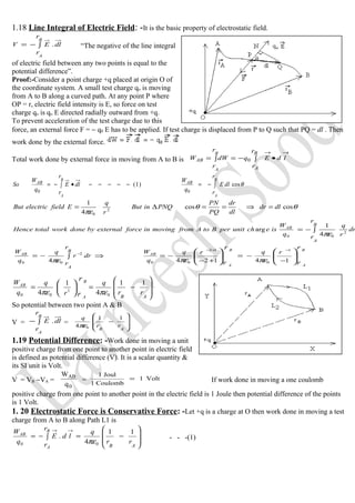
  • 1. 1.18 Line Integral of Electric Field: -It is the basic property of electrostatic field. dl r r EV B A .∫−= “The negative of the line integral of electric field between any two points is equal to the potential difference”. Proof:-Consider a point charge +q placed at origin O of the coordinate system. A small test charge qo is moving from A to B along a curved path. At any point P where OP = r, electric field intensity is E, so force on test charge qo is qo E directed radially outward from +q. To prevent acceleration of the test charge due to this force, an external force F = − q0 E has to be applied. If test charge is displaced from P to Q such that PQ = dl . Then work done by the external force. Total work done by external force in moving from A to B is ∫ •−=∫= →→B A AB r r ldEq r r dWW B A 0 ∫−=−−−−−•∫−= B A B A r r dlE q W dl r r E q W So ABAB θcos)1( 00 θθ πε coscos 4 1 2 0 dldr dl dr PQ PN PNQinBut r q EfieldelectricBut =⇒==∆= ∫−= B A r r dr r q q W isechunitperBtoAfrommovinginforceexternalbydoneworktotalHence AB 2 00 4 1 arg πε ⇒∫−= − B A r r drr q q WAB 2 00 4πε             − −= +− −= −+− 14124 1 0 12 00 rqrq q W B A B A AB r r r r πεπε         −==       AB rr q r q q W B A AB r r 11 4 1 4 0 1 00 πεπε . So potential between two point A & B V = dl r r E B A .∫− =         − AB rr q 11 4 0πε 1.19 Potential Difference: -Work done in moving a unit positive charge from one point to another point in electric field is defined as potential difference (V). It is a scalar quantity & its SI unit is Volt. V = VB −VA = 0 AB q W = Volt1 Coulomb1 Joul1 = If work done in moving a one coulomb positive charge from one point to another point in the electric field is 1 Joule then potential difference of the points is 1 Volt. 1. 20 Electrostatic Force is Conservative Force: -Let +q is a charge at O then work done in moving a test charge from A to B along Path L1 is         −=∫−= →→ AB rr q ld r r E q W B A AB 11 4 . 00 πε - - -(1)
  • 2. Work done in moving the test charge from B to A along L2 path is 0 BA q W = →→ ∫− ld r r E A B . =         − BA rr q 11 4 0πε -- (2) Total work done in moving the test charge over close path AL1BL2A is 000 q W q W q W BAABABA += 2&1 eqeqFrom 0 1111 4 00 =                 −+         −= ABBA rrrr q q WABA πε 0. 0 =−= ∫ dl c E q WABA The line integral of electric field along the closed path in electrostatic field is zero. Hence work done in moving a test charge along a closed path is zero ie work done is independent of the path. So electrostatic force is conservative force. 1.21Potential:- Work done in bringing a unit positive charge from infinite to any point in electric field is define as potential of the point(V). It is a scalar quantity & its SI unit is Volt. V = 0q W A∞ V = 0 ABA q W = Volt1 Coulomb1 Joul1 = If work done in moving a one coulomb positive charge from infinite to any point in the electric field is 1 Joule then potential of the point is 1 Volt. In c.g.s. System, unit of potential is stat volt. 1 stat volt = 300 volt. If work done in moving a one stat coulomb positive charge from one point to another point in the electric field is 1 erg then potential difference of the points is 1 Stat Volt. Electric potential of a point is equal to negative of the line integral of the electric field intensity from infinite to the points. In this case A r = ∞ , r B = r . V = ∫ ∞ →→ − r dl.E r q V r q V 00 4 111 4 πεπε =⇒      ∞ −= 1.21Potential due to a Point Charge: -Consider a point charge +q at O. OB = r . We have to find field intensity at point B. At point A electric field intensity )1( 4 1 2 0 −−−= x q E πε Along OA Work done in bringing a unit positive charge from A to C is dW = F . dx But F = − q0 E isBintpoofpotentialSodxE r q r dWBW 0∫∫ ∞ −= ∞ =∞ ∫ − == ∞ ∞ r B dx x q q W V 2 00 4 1 πε ⇒∫−= − Br Ar dxx q V 2 04πε ( ) rr r x q V xqxq V ∞ − ∞ +− ∞       =⇒ − −= +− −=      1 414124 0 1 0 12 0 πεπεπε r q V r q V 00 4 111 4 πεπε =⇒      ∞ −= Relation between E and potential gradient:- Since dW = − q0 E dr So dW/ q0 = E dr
  • 3. Potential difference dV = − E dr Hence dr dV E −= (i.e. E = − potential gradient) Potential Energy: - Work done in bringing a charge body from infinite to any point in electric field is defined as electrictrostatic potential energy of the point (U). VqWUsystemtheofenergypotentialSo q W V B B 0 0 === ∞ ∞ r qq Uor r qq U 21 0 0 0 . 4 1. 4 1 πεπε == Potential due to a group of charges: -Potential due to n charges at any point is V = V1 + V2 + V3 + - - - -       −−−−−−+++= 3 3 2 2 1 1 04 1 r q r q r q V πε Potential due to uniform distribution of charge: - dq is a small charge element, then potential at any point r dq V ∫= 04 1 πε . r dl VechlinearFor l ∫ = λ πε04 1 arg r ds VechsurfaceFor S ∫ = σ πε04 1 arg r dV VechvolumeFor V ∫ = ρ πε04 1 arg 1.22 Potential at a point due to an electric dipole: - Consider a dipole of charge –q & +q separated by a small distance 2l having a dipole moment p = 2ql . We want to find potential at point P which is at distance r from the centre of the dipole O. Let AP = r2 & BP = r1 AD⊥OP & BC⊥PO extended. r1 = OP + CO In ∆BCO CO = l cos θ So r1 = r + l cos θ - - - - - -(1) r2 = OP − CO In ∆BDO CO = l cos θ So r2 = r − l cos θ - - - - - -(2) Net potential due to the dipole ][ 4 1 120 r q r q VVV 21 − +=+= πε ] coscos [ 4 1 0 θθπε lr q lr q V + − − = ( )( )θθ θθ πε coscos coscos 4 0 lrlr lrlrq V +− +−+ ×= θ θ πεθ θ πε 222 0 222 0 cos cos 4 1 )cos( cos2 4 lr p V lr lq V − ×=⇒ − ×= lqpWhere 2×= Case-I If the point lies on the equatorial line i.e. θ = 90 so cos 90 = 0 . Hence potential V = 0 Case-II If the point lies on the axial line i.e. θ = 0 so cos 0 = 1 . Hence potential )(4 1 22 0 lr p V − = πε 1.23 Equipotential Surface:-the surface in electric field having same electric potential at each point is called equipotential surface. The locus of all those point which having same potential is defined as equipotential surface. Properties of equipotential surface:-(1) No work is done in moving a charge between any two points on equipotential surface. 0ABAB q/WVV =− But A and B are point on equipotential surface so 0WVVWsoVV ABAAABAB =⇒−== (2) A straight-line drawn normal to the equipotential surface will give direction of electric field at that point. (3)Electric field intensity and electric lines of force are parallel to each other & perpendicular to equipotential surface.
  • 4. 900cos 0cos0..0 0 == =−=−== θθ θ orwhenpossibleonlyisIt dsEqhencerdEqrdFsoWSince AB  (4) Equipotential surfaces are close together in the region where electric field is strong& are far apart in the weaker Field region. Since . 1 greaterbewillEthensmallisdrifsoconstantisdVIf dr Eso dr dV E ∴α= (5) If two equipotential surfaces intersect each other at a point, then there will be two normal at a point which will give two direction of electric field intensity (two value of potential) at same point. But electric field intensity is a vector quantity, which have only one direction. Hence two equipotential surfaces never intersect each other. 1.24 Conductors: -Those material which permit flow of electric charge through them are called conductor e.g. all the metals, salt solution &acid solution. These material posses large number of free electron. Insulators:-Those material which do not permits flow of electric charge through them are called insulator e.g. wood , plastic ,wax ,glass etc. These material posses negligibly small number of free electron hence these material are poor conductor of electricity. Dielectrics: - Dielectrics are those insulators, which transmit electric effect through them when they are placed in electric field e.g. water, glass, mica, PVC etc. When the dielectrics are placed in electric field charge is induced on the surfaces. 1.25 Behaviour of conductor in electric field: - (1) Inside a conductor electric field is zero: -When a conductor is placed in electric field of intensity E0 , free electrons are attracted by the positive side of the field (towards AC ). Hence positive charge is induced on DB side & negative charges on AC side. Due to this induced charge an internal electric field Ei develops in the conductor, which is opposite to main field E0. In metal equal but opposite charge is induces so E0 = E i , hence net electric field inside the metallic conductor is E = E0 – Ei = 0 . (Fig-1) (2) Net charge inside a hollow conductor is zero. From Gauss theorem 000. 00 =⇒= ∈ = ∈ =∫ q q soEconductorhollowainSince q SdE S  (3) Charge always lies on the outer surface of the conductor:-Consider a positively charged conductor. We will draw an imaginary surface just inside the surface of the conductor, it is called Gaussian surface. Since electric field inside a conductor is zero so net out ward electric flux through Gaussian surface is zero. Hence from Gauss theorem the net charges in side a conductor is zero. This shows that all charge lies on the outer surface of the conductor. (Fig-2) (4) When a conductor is placed in electric field then charge on the conductor is rearranged and finally the flow of charge stops. It is only possible when component of electric field E cos θ = 0 or Cos θ = 0 i.e. θ =90 hence electric field on the outer side of the conductor is perpendicular to the surface at every point. (5) Electric potential is constant within and at the surface of the conductors. tConsVhence dr dV soEconductortheinsidebut dr dV E tan00 ===−= (6) Electrostatic Shielding is the phenomenon of protecting a certain region of space from electric field. Electric field intensity inside a conductor in an electric field is zero. This property is used to protect electric instrument from external electric field by enclosing them in a hollow conductor. The hollow conductor is called Faraday cage e.g. during lightning it is safer to be inside a car or bus than to be in open ground or under tree. The metallic body of the vehicle will provide the electrostatic shielding. 1.26 Capacitance: -electric capacitance is the measure of the ability of the conductor to store charge on it. If charge on the conductor is zero, its potential is zero. As charge on the conductor increases gradually its potential also increases. At any instant charge on the conductor Q is directly proportional to its potential. Q ∝ V ⇒. Q = C V
  • 5. Where C = Q / V is a constant known as capacity or capacitance of the conductor. Its value depends on the size of the conductor and medium around the conductor. Its SI unit is Farad. If V = 1 Volt , then Q = C i.e. “ the amount of charge which is to be given to a conductor so that its potential increase by 1 volt is equal to capacity of the conductor”. If Q = +1 Coulomb & V = 1 Volt then C = = +1 Coulomb /1 Volt C = 1 Coulomb/Volt = 1 Farad “If 1 Coulomb of charge is given to a conductor so that its potential is increased by 1 volt then the capacity of the conductor is 1 Farad”. 1 micro Farad ( µF ) = 10−6 F , 1 Pico Farad = 10−12 F C.G.S. Unit of capacity is state Farad or e.s.u. of capacity. 1 Farad = 9 × 10¹¹ stat Farad 1.26 Principle of Capacitor (Condenser): - Capacitor, or electrical condenser is a device for storing a large amount of electric charge in small space. A capacitor consists of two metal plates separated by a non-conducting medium called dielectric. When one plate is charged with electricity from a direct-current or electrostatic source, the other plate will have induced on it a charge of the opposite sign; that is, positive if the original charge is negative and negative if the original charge is positive. Capacitors are produced in a wide variety of forms. Air, mica, ceramics, paper, oil, and vacuums are used as dielectrics, depending on the purpose for which the device is to be used. Principle: -Since capacity of a capacitor C = Q / V i.e. C ∝ 1 / V Hence capacity of a capacitor can be increased by decreasing its potential., this is basic principle of capacitor. It can be achieved by bringing an uncharged earthed conductor near the conductor. Consider a conductor, A which has +q charge & potential V. Another conductor B, is electrically neutral. If we try to bring a 1 C positive charge to the conductor A there is strong repulsion. So large amount of work has to be done i.e. potential is large. If conductor B is brought close to A, due to electrostatic induction –ve (bound) charge is induce toward left side. While +ve (free) charge is induce on right side. If B is connected to the earth so the free positive charge passes to the earth, now it has only negative charge. Now if we bring +1 C charge from infinite to the conductor A then there will be repulsion due to A as well as attraction due to B which decrease the repulsion by a large amount. Hence the amount of work done i.e. potential decreases by a large amount hence we can store a large amount of charge in small space. 1.27 Parallel Plate Capacitor: -This type of capacitor consist of two plane conductor (rectangular or circular) parallel to each other separated by a dielectric which is air in this case. {1}Consider a rectangular plate A connected to the source & plate B connected to the earth. Due to electric induction −q charge is induce on plate B if +q charge is given to plate A. Let air is the dielectric & area of each plate is ‘a’ and distance between them is d. So surface charge density of each plate is σ = q / a - - - -(i) {2}From Gauss’s theorem electric field at a point between the two plate E = σ /ε 0 .- - -(ii) )(}3{ )(arg 0 0 iv a dq VdEVisplatesthebetweendifferencepotentialSo iii a q Eso a q densityechsurfaceBut −−−−=⇒= −−−−−== ε ε σ d a CHence aqd q C V q CcapacitortheofcapacityThus 0 0/ }4{ ε ε ==⇒= If dielectric medium of dielectric constant K is introduced between the plates then d aK m CmediumtheincapacitortheofCapacity 0ε = Dependence of capacitance of Parallel palate capacitor:- (1) C ∝ a Since capacitance is proportional to area of plates so capacity can be increased by increasing area of plates.(2) C ∝ 1/d Since capacitance is inversely proportional to distance between the plates so capacity can be increased by decreasing distance between the plates.(3) ) C ∝ K Since capacitance is proportional to dielectric constant of the medium between the plates. so capacity can be increase by having dielectric medium of high dielectric constant.
  • 6. 1.28 Capacitance of cylindrical capacitor )/(log 2 0 ab l C e επ = where b & a are radius of outer & inner cylinder respectively. Capacitance of spherical capacitor ab ba C − = 04 επ where b & a are radius of outer & inner sphere respectively. Application of Capacitor: - [1] To eliminate sparking when a circuit containing inductor is broken i.e. ignition system of automobiles. [2] In power supply for smoothing the rectified current (D.C.) [3] To improve efficiency & power factor in a.c. circuits. [4] To produce rotating magnetic field. [5] To tune radio & TV circuits. [6] As a charge accumulator. [7] In electronics 1.28 Capacity of a spherical Conductor: - Consider a spherical conductor of radius ‘r’ & charge q is given to it so that its potential increases to V. Spherical conductor is an equipotential surface because all the point on this surface are equidistant from its centre. rC r q q V q CcapacityBut r q V 0 0 0 4 4 14 1 πε πε πε =⇒=== Hence capacity of a spherical capacitor is equal to 04πε time its radius in SI units. In c.g.s unit capacity of the spherical conductor is equal to its radius. Hence a spherical conductor behaves like a spherical capacitor with second conductor at infinite distance. 1.28 Energy of a charged conductor (Capacitor):- Consider a capacitor of capacity C having charge q on it. Then its potential V = q / C - - - - - (1) If we want to increase the charge by dq then we have to do work dW against the force of repulsion We know that potential V = dW / dq so dW = V dq isQQtoQfromconductortheingchindonetotalworkSo == 0arg ∫= Q dWW 0 ∫∫ ==⇒ QQ dqq CC dqq W 00 1       −=      = 2 0 2 1 2 1 2 0 2 Q C q C W Q WUenergypotentialasconductortheinstoredisdoneworkThis = C VC USoVCQBut C Q UcapacitorofenergyThus 222 2 1 2 1 === U = ½ CV2 Also U = ½ QV Combination:-If capacitors are connected in series or parallel then total energy is equal to sum of the energy of the capacitors. U = U1+U2 +U3+U4 + - - - In Series Combination:- C Q CCC Q C Q C Q C Q U 2 321 2 3 2 2 2 1 2 2 1111 2 1 2 1 2 1 2 1 =      −−−−++=−−−+++= In Parallel Combination:- U = ½ C1 V2 + ½ C2 V2 + ½ C3 V2 + - - - - - - 22 321 2 1 )( VCVCCC 2 1 U =−−−−+++= Energy Density:-Energy stored per unit volume is called energy density. Capacity of a parallel plate capacitor C then , Energy density = Energy/Volume 2 0 202 2 122 1       === d V da V d a da VC ε ε d V EfieldelectricBut = Hence 2 0 2 1 EdensityEnergy ε= 1.29 Sharing of charge between two conductor (Capacitor) & loss of energy:-Consider two conductor A & B of capacity C1 & C2 having charge Q1 & Q2 ,their potential are V1 & V2 respectively. So Q1 = C1 V1 - - - - - - - (1) Q2 = C2 V2 - - - - - -(2) [a]Charge after redistribution:-Now the two conductors are connected by a conducting wire so charges flow from higher potential to lower potential till their potential become same. Due to
  • 7. redistribution the common potential isV and charges becomes q1 and q2 respectively. So q1= C1 V - - - - (3) , q2 = C2 V- - - --(4) Dividing eq(3) by eq(4) q1/q2 =C1V/C2V Hence q1/q2 =C1/C2 )5( ..tanarg ,arg 2 21 1 2 211 11 2 211 −−−−      + + =⇒ + = + +=+ + = + C CC QQ q C CC q QQ So QQqqeitconsremainalwassystemtheofechtotal echofonconservatioflawfromBut C CC q qq propertiescompodendoApplying 2 2 2 2 22 2 2 Dividing eq4 by eq3 q2 / q1 =C2V / C1V Hence q2/q1 =C2/C1 1 21 1 21 q q C CCq propertiescompodendoApplying + = + ,argechofonconservatioflawfromBut 22 QQqqeitconsremainalwayssystemtheofechTotal +=+ 11..tanarg . 1 21 1 1 211 C CC QQ q C CC q QQ So 2 1 1 2       + + =⇒ + = + - - - - - - - (6) [b]Common Potential of the conductor V = Total charge / Total Capacity       + + =⇒      + + = 21 2211 21 21 CC VCVC V2&1eqFrom CC QQ V - - - - -(7) [c]Loss of energy: -Energy of conductors before joining are U1 = ½ C1 V1 2 - - - - - -(8) U2 = ½ C2 V2 2 - - - - - -(9) Energy of conductors after joining is U = ½ C V2 - - - -(10) Loss of energy ∆U = (U1 + U2 ) − U = ( ½ C1 V1 2 +½ C2 V2 2 ) − ½ (C1 + C1)V2 ( ) 2 21 2211 21 2 22 2 11 2 1 2 1 2 1       + + +−+=∆ CC VCVC CCVCVCU ⇒ ( ) 21 2 22112 22 2 11 2 1 )( 2 1 CC VCVC VCVCU + + −+=∆ ( ) )(2 ))(( 21 2 2211 2 22 2 1121 CC VCVCVCVCCC + +−++ = ( ) )(2 2) 21 21212 2 2 2 1 2 1 22 22 22 11 22 221 2 121 CC VVCCVCVCVCVCVCCVCC + ++−+++ = )(2 )2( )(2 2 21 21 2 2 2 121 21 2121 2 221 2 121 CC VVVVCC CC VVCCVCCVCC U + −+ = + −+ =∆ ( )2 21 21 21 )(2 VV CC CC U − + =∆ ( ) positivealawaysisVVSince 2 21 − So there is always loss of energy in redistribution of charge. According to the law of conservation of energy this loss is converted in to heat in connecting wire, light (sparking) & to produce some sound. 1.30a. Series combination of capacitor:-When first plate of first capacitor is connected to source & second plate of the first capacitor is connected to the first plate of the second capacitor, second plate of the second capacitor is connected to the first plate of the third capacitor and so on then this combination is known as series combination. Consider the capacity of three capacitors are C1 , C2 & C3 connected in series to a source between points A & B. Point B is connected to the earth so +Q & –Q charges are induce on the plates of capacitors. Potential difference between the plate of capacitors are V1 , V2 & V3 respectively. )3(,)2(),1( 3 3 2 2 1 1 −−−−=−−−−=−−−−= C Q V C Q V C Q V If C is equivalence capacity of series combination with charge +Q & -Q on its plates with potential difference
  • 8. V = Q / C - - - - - (4) Potential difference between A & B is V = V1 + V2 + V3 putting values from eq1,2,3&4       −−−+++=⇒      ++=+= 321321321 C 1 C 1 C 1 C 1 C 1 C 1 C 1 Q C Q C Q C Q C Q Hence in series combination, reciprocal of equivalent capacity is equal to sum of reciprocal of the individual capacity of the capacitors. 1.30b. Parallel combination of capacitor:-When first plate of all the capacitors are connected to source & second plate of the capacitors are connected to the earth then this combination is known as parallel combination. Consider the capacity of three capacitors are C1 , C2 & C3 connected in parallel to a source between point A & B. Point B is connected to the earth. Source supply +Q charge which will divide in three parts after reaching at point A. Let charge reaching on capacitors are Q1 , Q2 &Q3 respectively. Potential difference between the plates of capacitors is V, which is same & constant. Q1 = C 1 V - - - -(1), Q2 = C2 V - - - -(2) Q3 = C 3 V - - - -(3) Equivalence capacity of series combination is C with charge +Q & -Q on its plates with potential difference V, then Q = C V - - - - - (4) Total charge Q = Q1 + Q2 + Q3 = C 1 V + C2 V + C 3 V C V = V( C1 + C2 + C3 ) Hence C = C1 + C2 + C3 - - - - thus equivalent capacitance in parallel combination is equal to sum of individual capacity of the capacitors. 1.31Dielectrics: - Dielectric, or electrical insulators are those substances, which do not allow electric current to pass, but they allow electric effect to pass through them. When the dielectric is placed in an electric field, the electrons and protons of its constituent atoms reorient themselves, and in some cases molecules become similarly polarized. As a result of this polarization, the dielectric is under stress, and it stores energy that becomes available when the electric field is removed The effectiveness of dielectrics is measured by their relative ability, compared to vacuum, to store energy, and is expressed in terms of a dielectric constant, with the value for vacuum taken as unity. The values of this constant for usable dielectrics vary from slightly more than 1 for air up to 100 or more for certain ceramics containing titanium oxide. Dielectrics, particularly those with high dielectric constants, are used extensively in all branches of electrical engineering, where they are employed to increase the efficiency of capacitors. Polarisation: -The alignment of the dipole moment of the permanent or induced dipoles in the direction of the applied field is called polarization. Dielectric Constant (K):- The ratio of capacity of a parallel plate capacitor with any medium between the plates to the capacity of the same capacitor with air as a dielectric medium is define as dielectric constant. o m r C C mediumaasairwithcapacitoraofCapacity mediumawithcapacitoraofCapacity K ==)( ε Polarisation vector or Polarisation density is a vector quantity, which describes the extent to which the molecules of the dielectric become polarise by an applied electric field. ,atomanofmomentdipoleinducedispWherepN V p PvectornPolaristio → → → == N− number of atom per unit volume. Induced dipole moment developed per unit volume of the dielectric is defined as Polarisation vector. Its SI unit is C/m2 ENPEpBut 00 εαεα =⇒= Dielectric Medium Vacuum Ai r Paper Porcelain Water Mica Dielectric Strength (V/m) ∞ 0.8 14 4 80 160
  • 9. Electric susceptibility (χ ) : - EP χε0= While χ is a proportionality constant. χ describes the electric behaviour of the dielectric, it is a dimensionless quantity. Larger the value of χ , greater will be the Polarisation of the dielectric in the electric field. In vacuum χ = 0 ,because there is no medium in vacuum. Dielectric Strength:-The maximum value of the electric field intensity that can be applied to the dielectric without breakdown is called dielectric strength. Ability of a dielectric to withstand electric fields without losing insulating properties is known as its dielectric strength Non Polar Dielectric Polar Dielectric (1)If centre of gravity of positively charged nuclei coincides with centre of gravity of negatively charge nuclei, then it is called non−polar molecule. (1) If centre of gravity of positively charged nuclei does not coincides with centre of gravity of negatively charge nuclei, then it is called polar molecule. (2) H2 , N2 O2 etc (2) N2O , HCl, H2O , NH3 etc. (3) Due to their symmetric shape of the molecules, they do not posses permanent dipole moment. (3) Due to their asymmetric shape of the molecules, they posses permanent dipole moment. (4) In the absence of external electric field a non-polar molecule does not posses a permanent dipole moment. When it is placed in external electric field, nucleus (proton) moves along the direction of electric field while the electron move opposite to the electric field. Now the atom acquires a permanent dipole moment. (4) In the absence of external electric field polar molecule posses a permanent dipole moment and molecules are randomly arranged so that the net dipole moment is zero. When it is placed in external electric field these atomic dipole align them selves along the field 7 acquire net dipole moment.. Capacity of a parallel plate capacitor with a dielectric slab introduced between the plates: - {1} Consider a rectangular plate A connected to the source & plate B connected to the earth. Due to electric induction +q & -q charge induce on plate A & B respectively. Let air be the dielectric & area of each plate is ‘a’ and distance between them is d. So surface charge density of each plate is σ = q / a - - -(i) {2} From Gauss’s theorem electric field at a point between the two plate E0 = σ /ε0 .- - -(ii) )( )( arg 0 0 0 iv d a CcapacitortheofCapacity iii a q Eairinfieldelectricso a q densityechsurfaceBut −−−= −−−= = ε ε σ {3} If dielectric medium of dielectric constant K is introduced between the plates then. Under the application of external field the positive charged nucleus & cloud of negative electron of the atom slightly move toward negative & positive plate respectively. Now atoms are polarised. The internal + ve and - ve charge neutralizes each other. A layer of positive charge toward plate B and a layer of negative charge toward plate A remain un−neutralise. This un-neutralised charge constitute an internal electric field inside the dielectric 0εaK q Ei = )./(, sin,)( VqCcapacityitsincreasewhichdecreasesdiffernecepotential sodEVceEEEtoreducesfieldelectricnetSofield.mainthetooppositeisWhich i0 = ×=−= (4) Potential difference between the plates V = Potential difference in air Vo+ Potential difference in medium ][])([tantan tEtdEmediumincedisEairincedisEV ioio ×+−×=×+×=
  • 10. ])([])([ ][)]([ K t td a C K t td a q q C V q CcapacitorofcapacitySot aK q td a q V o o oo +− =⇒ +− = =×+−×= ε ε εε 1.31 Van de Graff Generator: - The American physicist Robert Jemison Van de Graff developed it in 1931. It is an electrostatic machine used in nuclear physics for the generation of extremely high voltages & energy of the order of 10 M eV or even more. It is also used to accelerate a beam of electrons, protons, or ions to bombard the nuclei in a small target. Principle: - (1) Charge always lies on the outer surface of the conductor: -When a charged conductor is brought into internal contact with a hollow conductor, the whole charge of the conductor transferred to the hollow conductor. This charge shifts immediately to the outer surface of the conductor. (2) Sharp point action of the metals: - Electric discharge (Corona effect) takes place in air or gases at pointed conductors due to sharp edge action (high surface charge density) of the conductor called as action of points. Construction: - It consists of a large highly polished hollow metal sphere S known as metal dome. This sphere is insulated from the ground with the help of high insulated supports .A long narrow belt of silk or rayon (insulator) passes over two pulley P1 and P2 .The pulley P2 is at the centre of sphere and P1 at ground level. The belt is kept moving continuously in clockwise direction by an electric motor M. B1 and B2 are two brass brushes with sharp edges .B1 is connected to positive poled of E.H.T source (104 volt). Working :−Due to sharp edge action B1 sprays positive charge on belt so it is called spray comb. The positive ions carried upwards by belt are collected by B2 that ‘s why it is called collecting comb. Since B2 is connected to the hollow conductor from inside therefore the charge is transferred to the conductor S. As more and more charge is transferred to the sphere S its potential goes on rising. With increase of charge on the sphere, it leaks away to the surrounding. To prevent the leakage the outer surface of dome is made extremely smooth so that there is no undue accumulation of charge at any point on the surface. In addition to this the apparatus is enclosed in a gas filled steel chamber at 15 atm. The gases may be methane, N2 , Freon ,sulphur hexafluoride etc. The maximum potential to which the sphere can be raised is reached when the rate of leakage of charge become equal to the rate at which charge is transferred to the sphere. Source of charge particle is kept at the head of a long tube T . The other end where the target nucleus is kept connected to earth. If V is the potential difference between the ends of the tube and q is the charge of the accelerated particle .The energy acquires by the charge particle is qV on reaching the other end of the tube. Now a days we can produce accelerators from 10 MeV to 3 billion eV. In India a generator installed at IIT Kanpur in 1970 is of 2 MeV. Uses: - 1) It is used to accelerate streams of charged particles such as proton, deuteron, electron and α- particle etc. 2) To produce high P.d 3) In research in nuclear physics. Limitation: - 1) Its size is very large (10 m height) so it is very difficult to operate it .2) Due to high potential it is dangerous. 3) We cannot accelerate neutral particles like neutrons. Combination of Charged Drops:−Let n identical drops each having Radius – r, Capacitance – c, Charge – q, Potential – v and Energy – u. If these drops are combined to form a big drop of Radius – R, Capacitance – C, Charge – Q, Potential – V & Energy – U then (1) Charge on big drop : nqQ = (2) Radius of big drop : rnR /31 = (3) Capacitance of big drop :
  • 11. cnC /31 = (4) Potential of big drop: cn nq C Q V 3/1 == , vnV /32 = (5) Energy of big drop: 23/23/12 )()( 2 1 2 1 vncnCVU == , unU /35 = . 02-ELECTROSTATIC POTENTIAL Line integral of an elect field along a closed path 1. A uniform electric field H exists between two charged plates as shown in the figure. What would be the work done in moving a charge 'q' along the closed rectangular path ABCDA? (2001) 1 Definition of electric potential 1. Is electric potential a vector or a scalar quantity?(93, 2000) 1 2. Name the physical quantity whose SI unit is Joule/Coulomb.(1998, 2000) 1 3. Define electric potential? (1993, 2001) 1 Potential at a point due to a point charge 1. Derive the expression for the electric potential at a distance V from a point charge 'Q'. (1993, 2001) 3 2. The electric potential at 0.9 m from a point charge is + 50 V. Find the magnitude and nature of charge. (1995) 3 3. A point charge 'q' is placed at O as shown. Is (VA − VB) positive, negative or zero, if 'q' is a (i) positive, (ii) negative charge? (2001) 2 4. A point charge ‘q’ is placed at O as shown in fig. Is VP – VQ positive or negative when (i) q > o (ii) q < o. Justify your answer. [2006](2 Potential at a point due to two point charges 1. Two point charges + 4 μ C and − 6 μ C are separated by a distance of 20 cm in air. At what point on line joining the two charges is the electric potential zero? (97) 2 2. Two point charges 4 μ C, −2 μ C are separated by a distance of 1 m in air. At what point on the line joining charges is the electric potential zero? (01) 2 3. Two point charges 3 × 10⁻⁸ C and −2 × 10⁻⁸ C are located 15 cm apart in air. Find at what point on the line joining these charges the electric potential is zero. Take potential at infinity to be zero. (02) 2 4.A uniform electric field E of 300 N/C is directed along PQ. A, B and C are three points in the field having x and y coordinates (in meters) as shown in the figure. Calculate potential difference between the points (i) and B and (ii) B and C. (2003) 5.Two points charge 4 µC & − 2 µC are separated by a distance in 1 m in air. Calculate at what point on the line joining the two charges is electric potential zero.[07](2 Potential at a point due to many point charges 1. Calculate the potential at the centre of a square of side √(4.5) which carries at its four corners charges of +5 × 10⁻⁹ C, + 2 × 10− 9 C, −5×10⁻⁹ C and − 7 ×10⁻⁹ C respectively.(2000) 2 2. Calculate the potential at the centre of a .square of a side √2 m, which carries at its four corners charges of +2 nC, +1 nC, −2 nC and −3 nC respectively. (2000) 2 3. 2 mC charge is placed at each corner of a square ABCD of side 2 √2 cm. Calculate electric potential at the centre O of the square. (2003) 2 Potential at a point due to an electric dipole 1.Derive an expression for the electric potential at a point along the axial line of an electric dipole. (2000, 01, 02, 08) 3 2.Show mathematically that the potential at a point on the equatorial line of an electric dipole is zero.(01) Equipotential surfaces 1. What is the shape of Equipotential surfaces for a given point charge (95, 2000) 1 2.An infinite plane sheet of charge density10−8 C/m2 , is held in air. In this situation how far apart are two equipotential surfaces, whose p.d. is 5V? (99) 2 3. Draw an equipotential surface in a uniform electric field.(1999, 2000) 1 4. What is the amount of work done in moving a 100 μ C charge between two points 5 cm apart on an equipotential surface? (2000) 1 5. Show that the electric field is always directed perpendicular to an equipotential surface.(2001)2 6. What would be the work done- if a point charge + q is taken from a point A to point B on circumference of a circle with another point charge + q at the centre? (01)1 7. What is an equipotential surface? (2001, 03) 1 8. A 500 µ C Charge is at the centre of a square of side 10cm. Find the work done in moving a charge of 10 µ C
  • 12. between two diagonally opposite points on the square. 2008 (1 9. What is the electrostatic potential due to an electric dipole at an equatorial point? 2009(1 Misc. Qs on electric potential 1. Obtain an expression for the potential at a point due to a continuous distribution of charge.(92) 5 2. Can electric potential at any point in space be zero while intensity of electric field at that point is not zero? (1992) 1 Definition of electric potential energy 1. What is the S. I. unit for energy? (1987) 1 2. Define electron-volt. (1990) 1 Electric P.E. of an isolated point charge 1 . S 1 and S2 are two hollow concentric spheres enclosing charges Q and 2Q respectively as shown in the figure. (i) What is the ratio of the electric flux through S1 and S2? (ii) How will the electric flux through the sphere S1 change, if a medium of dielectric constant 5 is introduced in the space inside S1. In place of air? (02)2 Electric P.E. of a point charge, Electric potential energy of point charges, P.E. change: Pt. Charge: fixed uniform field, P.E. change: Pt. Charge: non- uniform field, P.E. of 2 point charges: fixed non- uniform field, P.E. of n point charges: fixed non- uniform field 1. Two point charges + 10 μ C and −10 μ C are sepa rated by a distance of 40 cm in air. (i) Calculate the electrostatic potential energy of the system, assuming the zero of the potential energy to be at infinity, (ii) Draw an equipotential surface of the system.(2004) 2 Work: point charge from one potential to another 1. The amount of energy that would be imparted to an electron on being accelerated through a potential difference of one volt is called (1988) 1 2. Two positive charges of 0.2 μ C and 0.01 μC are placed 10 cm. apart. Calculate the work done in reducing their distance to 5cm. (1992) 2 3. The work done in moving a charge of 3C between two points is 6 J. What is the potential difference between the points? (1993) 1 4. A proton placed in a uniform electric field of 2 × 10 3 N/C, moves from a point A to B in the direction of electric field. If AB = 0.05m, calculate the (i) potential difference between A and B, and (ii) work done in moving the proton from A to B. (98)2 5. Two point charges A and B of value +5×10⁻⁹ C and + 3 × 10− 9 C are kept 6 cm apart in air. Calculate the work done when charge B is moved by 1cm towards charge A. (2000) 2 6. Two point charges A and B of value +5μC and +6μC are kept 12 cm apart in air. Calculate the work done when charge B is moved by 2 cm towards charge A. (2000) 2 7. If a point charge +q, is taken first from A to C and then from C to B of a circle drawn with another point charge +q as center, then along which path more work will be done? (2001) 1 8. How much work is done in moving a 500 μC charge between two points on an equipotential surface. (02)1 Conservation of energy 1. What potential difference must be applied to produce an electric field that can accelerate an electron to one - tenth of velocity of light?(92) 2 2. If a charge +Q is revolved once round another charge q in a circle of radius R, how much work is done?(92)1 3.An α-particle and a proton are accelerated through the same potential difference. Calculate ratio of velocities acquired by the two particles.(97)2 To calculate field from a given potential distribution. 1. Find the electric field between two metal plates 3 mm. Apart, connected to a 12 V battery.(1993) 1 2. The electric field at a point due to a point charge is 40 N/C and electric potential at that point is 20 J/C. Calculate the distance of the point from the charge and the magnitude of the charge.(96) 2 3. Two protons A and B are placed between two parallel plates having a potential difference V as shown in the figure. Will these protons experience equal or unequal force? (1998) 1 Misc. Gues. on electric field and potential 1. At a point due to a point charge, values of electric field intensity and potential are 25 N/C & 10 J/C respectively. Calculate (i) magnitude of the charge, and (ii) distance of the charge from the point of observation. (2002) 2 03-CAPAC8TOR & CAPACITANCE Definition of electric capacitor, capacitance, etc. 1. Write the physical quantity which has as its unit coulomb/ volt. Is it a vector or a scalar quantity? (1992, 98) 1 2. Give S.I. unit of capacitance. (93, 96, 99, 2001) 1 Principle of a capacitor
  • 13. 1.Sketch a graph to show how the charge ‘Q’ acquired by a capacitor of capacitance 'C varies with increase in potential difference between its plates. (2003) 1 2.The graph shows the variation of voltage 'V’ across the plates of two capacitors A and B versus increase of charge. ‘Q' stored on them. Which of the two capacitors has higher capacitance? Give reason for your answer.( 2004)2 Uses of a capacitor 1. Describe any two uses of a capacitor. (1992) 2 Dielectric constant 1. How is dielectric constant expressed in terms of capacitance of a capacitor?(1992, 95, 96. 01) 1 2. The dielectric constant of a medium is unity. What will be its permittivity? (1992) 1 3. Define 'dielectric constant 'of a medium in terms of force between electric charges.(1997) 1 Capacitance of a parallel plate capacitor 1. What are the factors on which capacitance of a parallel plate capacitor depends? Also give the formula. (1990, 91, 92) 1 2. What is the area of the plates of a parallel plate condenser of capacity2F and with separation between the plates 0.5cm? Why do ordinary capacitances have capacitance of the order of microfarads? (1990) 3 3. Derive an expression for the capacitance of a parallel plate capacitor. (1992, 94) 3 1. Explain the principle of a capacitor. (1994) 2 2. Define capacitance. (1990, 92, 95, 97} 1 4. A parallel plate capacitor is charged to a potential difference 'V’ by a d.c. source. The capacitor is then disconnected from the source. If the distance between the plates is doubled, state with reason how the following will change: (i) electric field between the plates, (ii) capacitance and (iii) energy stored in the capacitor.(2001) 3 5. Obtain the expression for the capacitance of a parallel plate capacitor. (2003) 2 6. Two rectangular metal plates, each of area A, are kept parallel to each other at a distance 'd' apart to form a parallel plate capacitor. If the area of each of the plates is doubled and their distance of separation decreased to 1/2 of its initial value, calculate the ratio of their capacitances in the two cases, (2003) 2 7. A parallel plate capacitor is to be design with a voltage rating 1 kw using a mater 8. ial of dielectric constant 3 and dielectric strength about 107 vm-1 . For safety we would like the field never to exceed say, 10% of the dipole strength. What minimum area of the plates is required to have a capacitance of 50 pF? [2005] (2 9. A 4 µF capacitor is charged by a 200 v supply. The supply is then disconnected and the charged capacitor is connected to another uncharged 2 µF capacitor. How much electrostatics energy of the first capacitor is loss in the process of attaining t steady situations. [2005] (2 10. A parallel plate capacitor with air between the plates has a capacitance of 8pF. Half now reduces the separation between t plates and the space between them is filled with a medium of dielectric constant 5. Calculate
  • 14. the value of capacitance of the capacitor in the second case. [2006](2 11. A parallel plate capacitor is charged by a battery. After some time the battery is disconnected and a dielectric slab of dielectric constant K is inserted between the plates. How would (i) the capacitance, (ii) the electric field between the plates and (iii) the energy stored in the capacitor, be affected? Justify your answer. 2009(3 Capacitance of a spherical capacitor 1. Calculate the capacitance of a spherical capacitor consisting of two concentric spherical shells of radii a and b, with b > a. (1990) 5 Capacitance of an isolated sphere 1. Can a metal sphere of radius 1 cm hold a charge of one coulomb? Justify your answer. (1992) 2 2. A and B are two conducting sphere of the same radius, A being solid and B hollow. Both are charged to the same potential. What will be the relation between the charges on the two spheres? (2001) 1 Capacitance of a cylindrical capacitor 1. Derive an expression for the capacitance of a cylindrical capacitor.(1992) 5 Parallel plate capacitor filled with dielectric 1. Discuss how the presence of a dielectric affects the capacitance of a parallel-plate capacitor. (1985, 88, 97, 90) 2 2. Derive an expression for the capacitance of a parallel plate capacitor filled with a dielectric. (1992, 93, 94, 97, 99, 01) 3 3.Explain why the polarization of a dielectric reduces the electric field inside the dielectric.(1999) 2 Explain the underlying principle of working of a parallel plate capacitor. If two similar plates, each of area A having surface densities + σ and - σ are separated by a distance d in air, write expression for (a)The electric field at points between the two plates. (b) The potential difference between the plates (c)The capacitance of the capacitors so formed.[2007](5 Capacitor with a dielectric/conducting plate placed inside 1. What is a dielectric? A dielectric slab of thickness t is kept between plates of a parallel plate capacitor separated by distance‘d’. Derive the expression for the capacity of the capacitor for t << d. (1993) 5 2. A conducting slab of thickness 't' is introduced without touching between the plates of a parallel plate capacitor, separated by a distance 'd’ (t < d). Drive an expression for capacitance of the capacitor.(01) 3 Miscellaneous Question on capacitance 1.A parallel plate capacitor, when there is vacuum between the plates, has capacitance C. What will be the value of its capacitance, when, (i) distance d between the plates is doubled; (ii) a sheet of thickness t of a dielectric of relative permittivity K, is introduced between the plates. (1995) 2 2.In a parallel plate capacitance potential difference of 102 V is maintained between the plates. What will be the electric field at points A and B? (95)1 3.Calculate the voltage needed to balance an oil drop carrying 10 electrons when located between the plates of a capacitor which are 5mm apart, (g = 10 m/s) the mass of oil drop is 3 × 10−|6 kg. (1995) 2 4.In a parallel plate capacitor, the capacitance increases from 6 microfarad to 60 microfarad, on introducing a dielectric medium between the plates. What is the dielectric constant of the medium (1996) 1 Series & parallel combinations of capacitors 1. When two capacitors of capacitance C1. and C2, are connected in series the net capacitance is 3 mF; when connected in parallel its value is 16 mF. Calculate the value of C1, and C2,.(2000) 2 (a) Eq. capacity of capacitors in parallel/Series 1. What is the capacity of (i) a series combination. and (ii) A parallel combination, of n capacitances C1,C2,…….Cn (1990, 93) 2 2.State Gauss' theorem for electrostatics. Hence obtain expression for the force between two point charges. (1991) 5 3. Three capacitors of capacitances X1, X2 are connected (i) in series and (ii) in parallel. Derive expression for the equivalent capacitance X for each of these combinations.(1991, 92, 94) 5 4. Write two applications of capacitors in electrical circuits. (1994) 5 Eq. Capacity of a network of capacitors 1. Obtain the equivalent capacitance for the following network. For 300 V supply, determine the charge and voltage across each capacitor. (90)3 2.What is meant by the capacity of a conductor? Two capacitors of 0.4 μF and 0.6μF are connected in parallel. Find the capacitance of combination.(91)3 3.Four capacitors are connected as shown in the figure given below; Calculate the equivalent capacitance between the points X and Y.(2000) 2 3. Misc. Q's on combination of capacitors 1. Two capacitors of equal capacitance when connected in series have net capacitance C1 and when connected in parallel have net capacitance C2, What is the value of C1/C2? (1993, 95) 3
  • 15. 2. Calculate the capacitance of the capacitor C in the figure, if the equivalent capacitance of the combination between A and B is 15μF.(1994) 2 3. Calculate the capacitance of the capacitor C in the figure. The equivalent capacitance of the combination between P and Q is 30μF. (1995) 5 4. Find the equivalent capacitance of the combination of capacitors between the point A and E as shown in the figure. Also calculate the total charge that flows in the circuit when a 100 V battery is connected between the points A and B.(02)3 Energy stored in a capacitor 1. A 900 pF capacitor is charged by a 100 V battery. How much electrostatic energy is stored by the capacitor? (1990) 1 2. Show that energy density in a parallel plate capacitor is ½ ε0E2 , where E is the electric field. (1992, 98) 5 3. How much energy will be stored by a capacitor of 470μF when charged by a battery of 20 V? (1994) 1 4. Hence derive the expression for the energy density of a capacitor. (1992, 95, 96) 5 5. (i) Derive an expression for the energy stored in a parallel plate capacitor with air as the medium between its plates, (ii) Air is replaced by a dielectric medium of dielectric constant K. How does it change the total energy of the capacitor? (1997) 5 6. Obtain also the expression for the energy stored in a parallel plate capacitor with a dielectric medium of dielectric constant 'k' between its plates. (2001) 2 7. Prove that the total electrostatic energy stored in a parallel plate capacitor is 1/2 CV2 . 8. (1992, 93, 95, 2000, 01, 02) 2 9. 5 µF capacitor is charged by a 100 v supply. The supply is then disconnected then the charge capacitor is connected to another uncharged 3 µF capacitor. How much electrostatic energy of the first capacitor is lost in the process of attaining the steady situations? [2005](2 10. Two capacitor of capacitance 6 µF and 12 µF are connected in series with the battery. The voltage across 6 µF capacitor is 2 volts. Compute the total battery voltage. [2006](2] Energy stored in capacitors: series / parallel 1. Sketch graph (or otherwise) to show how charge Q given to a capacitor of capacity C varies with the potential difference V. (1992, 2000) 3 2. Three capacitors of capacitances C1, C2, and C3 are connected (i) in series, (ii) in parallel. Show that the energy stored in the series combination is the same as that in the parallel combination.(2003) 5 Energy & P.d. in capacitors: various cases 1. A capacitor is charged to potential V. The power supply is disconnected and the capacitor is connected in parallel to another uncharged capacitor, (i) Derive the expression for the common potential of the combination of capacitors, (ii) Show that total energy of the combination is less than the sum of the energy stored in them before they are connected. (1993) 5 2.A 80μF capacitor is charged by a 50 V battery. The capacitor is disconnected from the battery and then connected across another uncharged 320 μF capacitor. Calculate the charge on the second capacitor. (1994) 2 3. Capacitors P, Q and R have each a capacity C. A battery can charge the capacitor P to a potential difference V. If after charging P. the battery is disconnected from it and the charged capacitor P is connected in following separate instances to Q and R (i) to Q in parallel and {ii) to R in series, then what will be the potential differences between the plates of P in the two instances? (1997) 2 4. Derive an expression for the energy stored in a parallel plate capacitor. Assuming that the capacitor is disconnected from the charging battery, explain how the p.d. across the plates, and in the parallel plate capacitor change, when a medium of dielectric constant 'K' is introduced between the plate 5. A 10μFcaparitor is charged by a 30V d.c. supply and then connected across an uncharged 50 μF capacitor. Calculate (i) the final potential difference across the combination, and (ii) the initial and final energies. How will you account for the difference in energy? C2004 ) 3 Van de Graff generator 1.With help of a labeled diagram, describe the construction and working of a van de Graff generator.(1986, 90, 93, 96, 99, 03) 5 How is the leakage of charge minimized from